Kawasaki 840067 User Manual
Page 5
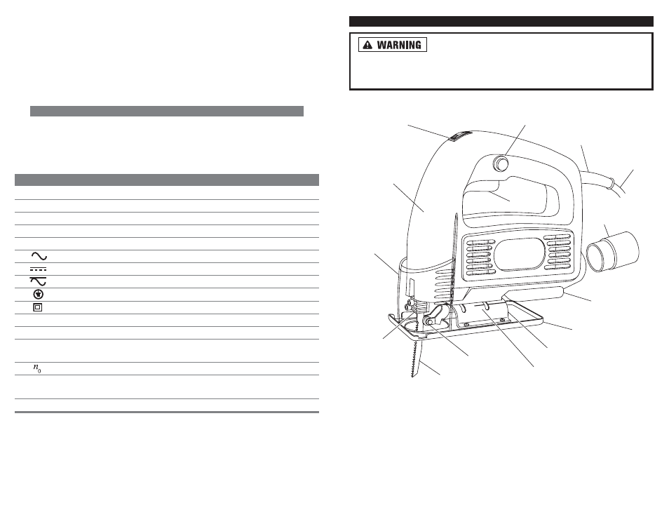
FUNCTIONAL DESCRIPTION
Disconnect the power plug from the AC power source
before any assembly, adjustments, or adding/removing accessories.
Following this preventative step reduces the risk of the saw coming on acciden-
tally and the risk of damage to the workpiece and injury to the operator.
Note: For tool specifications, refer to the nameplate on the jigsaw.
8
7
Make sure all adjusting screws on the jigsaw are firmly tightened. Failure to
tighten the adjustment screws can cause the blade to disengage from its holder
possibly damaging the jigsaw or causing injury to the operator.
When removing the blade or other accessories from the jigsaw, avoid contact
with the skin. Always wear protective gloves when handling the jigsaw or any
accessory. The blade can become hot after prolonged use and will cause burns.
SYMBOLS
IMPORTANT: Some of the following symbols may be used on your tool. Please
study them and learn their meaning. Proper interpretation of these symbols will
allow you to operate the tool better and safer.
SYMBOL
NAME
EXPLANATION
V
Volts
Voltage (Potential)
A
Amperes
Current
Hz
Hertz
Frequency (Cycles per Second)
W
Watt
Power
Kg
Kilograms
Weight
Alternating Current
Type of Current
Direct Current
Type of Current
Alternating or Direct Current
Type of Current
Earthing Terminal
Grounding Terminal
Class II Construction
Denotes Double Insulation
min
Minutes
Time
s
Seconds
Time
Diameter
Size of Drill Bits,
Grinding Wheels, etc.
No load speed
No-load Rotational Speed
.../min
Revolutions per Minute
Revolutions, Surface Speed,
Strokes, etc. per Minute
1,2,3, …
Ring Selector Settings
Speed, Torque or Position Settings
0
Speed Control
Switch
Trigger
Trigger Lock
Hex Wrench
Storage
Power Cord
Strain Relief
Power
Cord
Vacuum
Attachment
Bevel Markings
Baseplate
Roller Guide
Blade
Blade Guard
Blade
Holder
Gear
Housing
Bevel Plate
FIGURE 1.
JIGSAW COMPONENTS