Kirby Morgan 37 User Manual
Page 13
80
© Copyright 1970-2008 Kirby Morgan Dive Systems, Inc. All rights reserved. Document # 080508001
Kirby Morgan 37 & 57
7.7 SuperFlow 350
Demand Regulator
7.7.1 General Regulator Information
While the regulator systems on all Kirby Morgan hel-
mets are simple and highly reliable, the breathing re-
sistance will increase if the demand regulator on your
helmet is not maintained or adjusted properly. The
demand regulator must receive regular maintenance
to assure the best performance possible. However, in
the event the demand regulator is damaged, there is
always a backup supply of steady flow gas available
from the defogger valve.
If the regulator does not breathe easily, the diver can-
not work hard and will tire rapidly. Simply put: If the
demand regulator does not work properly the diver
cannot work properly. This makes the maintenance
of the demand regulator assembly essential.
For the gas inlet valve and adjustment system to oper-
ate properly, the components in the demand regulator
MUST be in good condition and MUST be periodi-
cally inspected and adjusted.
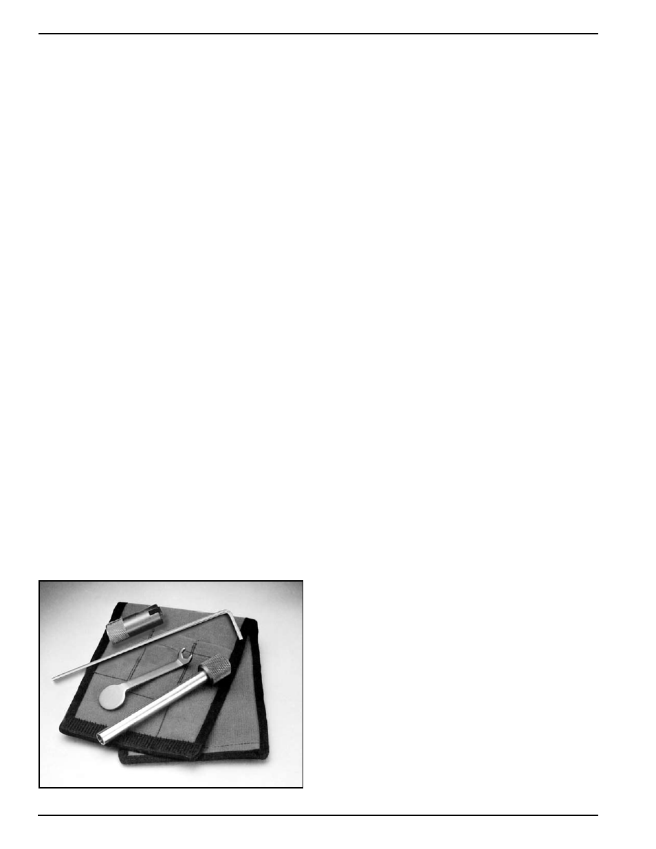
Four special tools, the inlet valve holder (Part #525-
616), the regulator adjustment wrench (Part #525-611),
the socket wrench (Part #525-612), and the castle
wrench (Part #525-618) should be used to work on
the SuperFlow 350 regulator whenever possible.
Disassembly, assembly, and adjustment can be done
without these tools, but the work is much easier and
the adjustment is better if these tools are used. The
above 4 tools are available together along with a tool
case. The “Tool Kit with Pouch” is Part #525-620.
This kit is included with each new Kirby Morgan
helmet that is equipped with the SuperFlow 350
regulator.
Tool Kit with pouch - Part #525-620.
7.7.2 SuperFlow 350 Demand Regulator Test
for Correct Adjustment, Fully Assembled
To maintain optimum performance of the demand
regulator, it should be checked for proper function
and adjustment prior to commencement of diving
each diving day, in accordance with the KMDSI Daily
Set Up and Functional Checklist. See the Dive Lab
website (www.divelab.com) for the latest procedures
for set-up.
Check the regulator for adjustment and proper func-
tion with the assembly complete, and supplied with a
breathing gas supply pressure of 135 to 150 p.s.i.g.
NOTE: 135 to 150 p.s.i.g. over ambient is the stan-
dard supply pressure to be used when adjusting
all KMDSI helmets and band-mask equipped with
the SuperFlow 350 regulator. See Section 2.5 for
recommended pressures during use.
NOTE: When storing the helmet for any length of
time, ensure that the regulator adjustment knob is
turned “out” fully counterclockwise to avoid stressing
the bias springs. This will prolong the life of both the
inlet valve, seat, and bias springs.
1) Rotate the regulator adjustment knob in, towards
the regulator body.
2) Ensure the supply pressure is connected and prop-
erly adjusted to 135 to 150 p.s.i.g.
3) Turn on the gas supply.
4) Rotate the adjustment knob out counterclockwise
slowly, until a slight steady flow develops.
5) Slowly rotate the adjustment knob in clockwise,
until the free flow stops. Lightly depress the purge
button several times and ensure the gas flow has
stopped.
6) Lightly depress the purge button. There should be
between 1/16” and 1/8” free travel in the button before
gas flow starts. When the button is fully depressed, a
strong surge of gas must be heard.
7) If the purge button travels less than 1/16” or greater
than 1/8” before free flow is heard, the demand regula-
tor requires internal adjustment, per this chapter.