Connecting wires to terminals – Kenwood DUAL DIN SIZED DPX502U User Manual
Page 35
English
|
35
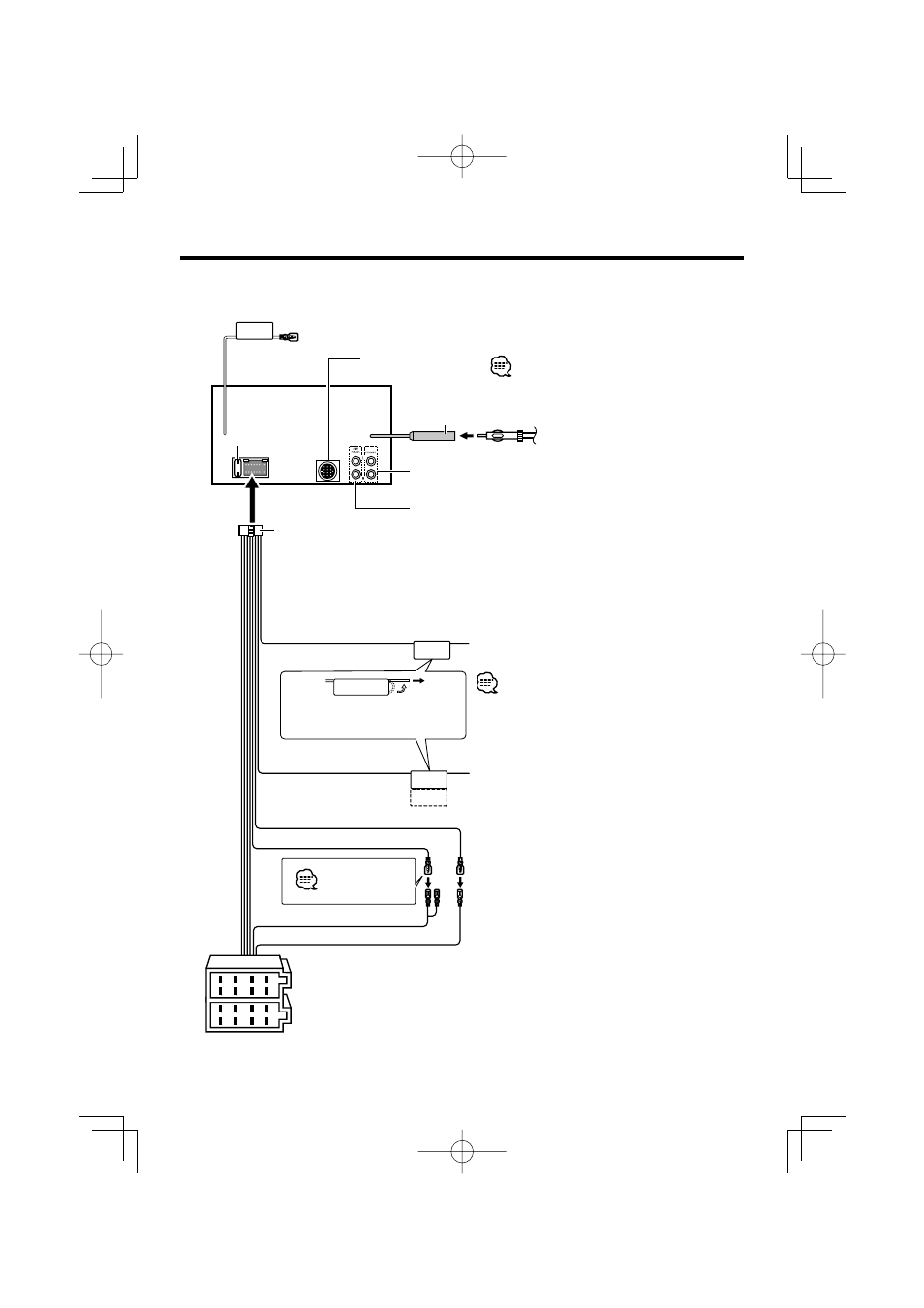
Connecting Wires to Terminals
REMO.CONT
P.CONT
ANT.CONT
MUTE
1
2
3
4
5
6
7
8
1
2
3
4
5
6
7
8
Battery wire (Yellow)
Ignition wire (Red)
FM/AM antenna input (JASO)
Antenna Cord
To connect the Kenwood navigation system, consult
your navigation manual.
Wiring harness
(Accessory
1)
If no connections are made, do not
let the wire come out from the tab.
Power control/Motor antenna
control wire (Blue/White)
TEL mute wire (Brown)
Connect either to the power control terminal
when using the optional power amplifier, or to the
antenna control terminal in the vehicle.
Connect to the terminal that is grounded when
either the telephone rings or during conversation.
A–7 Pin (Red)
A–4 Pin (Yellow)
Connector A
Connector B
See next page
Steering remote control (Light Blue/Yellow)
To Kenwood disc changer/
External optional accessory
To connect these leads, refer to the relevant
instruction manuals.
Rear left output /Sub Woofer left output (White)
Rear right output /Sub Woofer right output (Red)
Fuse (10A)
Front left output (White)
Front right output (Red)