Kenwood KDC-4060RG User Manual
Page 23
— 23 —
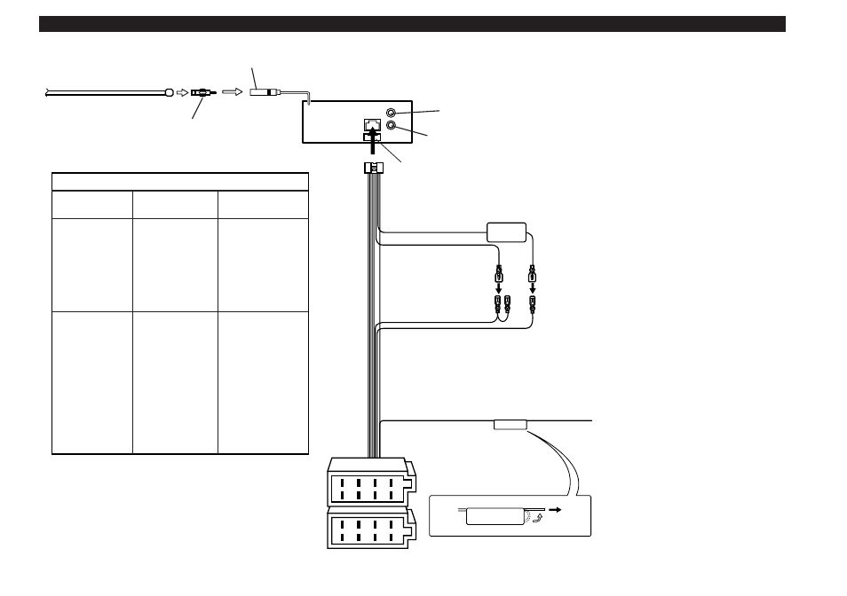
Connecting Cables to Terminals
1
2
3
4
5
6
7
8
1
2
3
4
5
6
7
8
P.CONT.OUT
Rear right output (Red)
Rear left output (White)
Connector Function Guide
Pin Numbers for
ISO Connectors
Cable Colour
Functions
External Power
Connector
A–4
A–5
A–7
A–8
Speaker
Connector
B–1
B–2
B–3
B–4
B–5
B–6
B–7
B–8
Yellow
Blue/White
Red
Black
Purple
Purple/Black
Gray
Gray/Black
White
White/Black
Green
Green/Black
Battery
Power Control
Ignition (ACC)
Earth (Ground)
Connection
Rear Right (
+
)
Rear Right (
–
)
Front Right (
+
)
Front Right (
–
)
Front Left (
+
)
Front Left (
–
)
Rear Left (
+
)
Rear Left (
–
)
Battery cable (Yellow)
Ignition cable (Red)
FM/AM antenna input
Antenna Cord (ISO)
Antenna Conversion Adaptor (ISO–JASO)
(Accessory4)
Wiring harness
(Accessory1)
If no connections are made, do not
let the cable come out from the tab.
Power control cable
(Blue/White)
When using the optional power amplifier,
connect to its power control terminal.
A–7 Pin (Red)
A–4 Pin (Yellow)
Connector A
Connector B
Fuse