Kawasaki 840276 User Manual
Page 7
O
OP
PE
ER
RA
AT
TIIN
NG
G T
TH
HE
E JJIIG
GS
SA
AW
W
D
Diisscco
on
nn
neecctt tth
hee p
po
ow
weerr p
pllu
ug
g ffrro
om
m tth
hee A
AC
C p
po
ow
weerr sso
ou
urrccee
b
beeffo
orree aan
nyy aasssseem
mb
bllyy,, aad
djju
ussttm
meen
nttss,, o
orr aad
dd
diin
ng
g//rreem
mo
ovviin
ng
g aacccceesssso
orriieess..
Following this preventative step reduces the risk of the saw coming on acciden-
tally and the risk of damage to the workpiece and injury to the operator.
A
AD
DJJU
US
ST
TIIN
NG
G S
SP
PE
EE
ED
D
The operating speed of the jigsaw
can be varied by using the Speed
Control Switch located on the top of
the jigsaw. Turn the speed control
from 0 to 6 to set the speed. On
most cuts, such as wood and metal,
the faster speed works best. On
other materials, such as plastic or
laminants, a slower speed might be
necessary to reduce vibration and
make smoother cuts.
O
OP
PE
ER
RA
AT
TIIN
NG
G T
TH
HE
E O
ON
N // O
OFFFF S
SW
WIIT
TC
CH
H
Plug the jigsaw into an approved 115
V AC outlet. This tool is double
insulated and equipped with a
polarized plug (one blade is wider
than the other). Double insulation
eliminates the need for a special
three-wire grounded power supply.
Holding the jigsaw by the insulated
handle, squeeze the trigger to turn
the jigsaw O
ON
N and release the trigger
to turn the jigsaw O
OFFFF. Allow the
blade to reach the maximum set
speed before bringing it in contact
with the workpiece.
P
PE
EN
ND
DU
UL
LU
UM
M S
ST
TR
RO
OK
KE
E A
AD
DJJU
US
ST
TM
ME
EN
NT
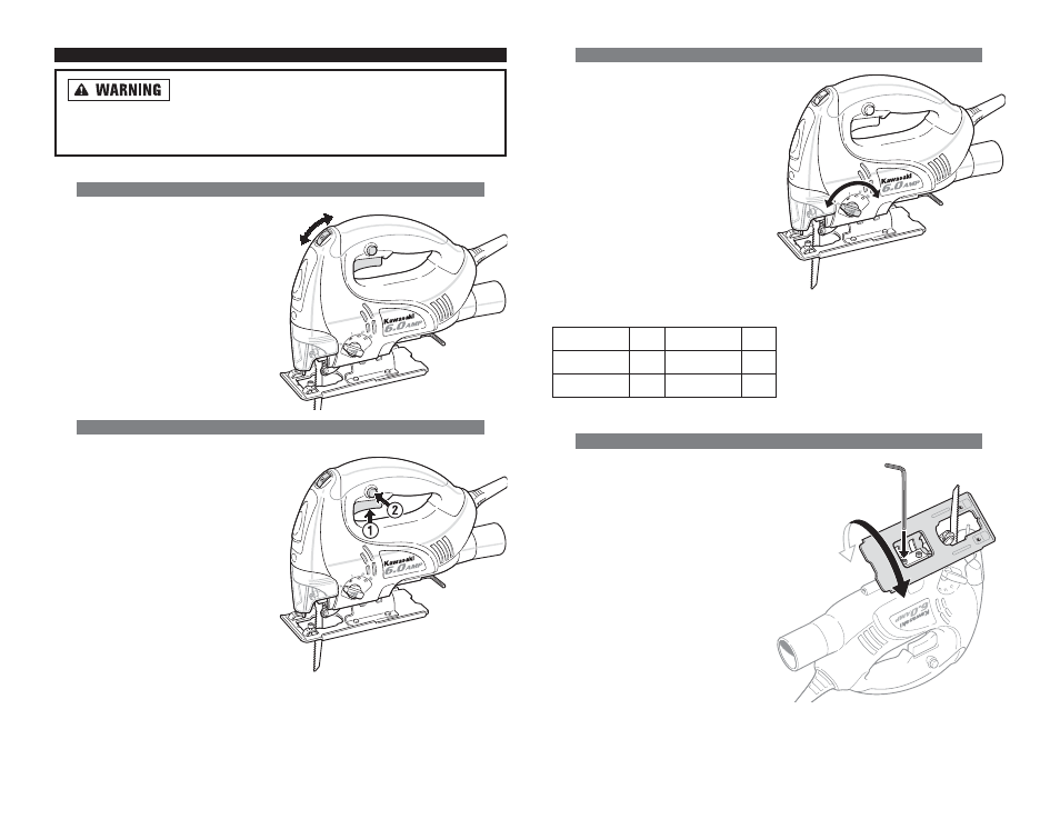
T
Together with the electronic speed
regulation, the pendulum stroke
adjustment helps to set the best
combination of blade speed and
aggressiveness needed to achieve a
desired cut rate and fineness. The
pendular knob is used to make the
adjustment. The best pendulum
stroke setting for the particular work
to be carried out can be obtained
from the following table. When using
a knife blade, the pendulum setting
should be 0. We recommend the use
of appropriate lubrication for cutting
metal.
S
SA
AW
W S
SH
HO
OE
E // P
PL
LA
AT
TE
E A
AD
DJJU
US
ST
TM
ME
EN
NT
T
Disconnect the unit from the power
supply. Raise the safety guard and
loosen the hex screw on the shoe
plate with the hex wrench. Pull the
shoe plate backward and set the
desired angular adjustment according
to the scale or push the shoe plate
forward for fixed Locks at 0°, 15°, 30°
or 45°. Tighten the hex screws again.
Always replace the hex wrench in the
hex wrench holder on the shoe plate
immediately after use.
11
12
Sheet metal 0
Steel
0- I
Aluminium
I-II
Plastic
I-II
Plywood
0- I Wood
I-III