Kawasaki 840276 User Manual
Page 6
A
AT
TT
TA
AC
CH
HIIN
NG
G T
TH
HE
E B
BL
LA
AD
DE
E
1. Firmly grip the plastic blade guard and slide it up to expose the blade clamp.
2. Using a hex wrench (provided in a slot beneath the motor), loosen the two hex
socket-head screws on the blade clamp until it slides forward enough to open a
slot for the blade.
3. Insert the blade into the blade clamp with the cutting edge facing to the front of
the jigsaw.
4. Using a hex wrench, securely tighten the two hex socket-head screws on the
blade clamp.
5. Using a hex wrench, loosen the two hex socket-head screws holding the bottom
board and the guide roller on the saw housing.
6. Slide the guide roller forward until the back of the blade fits loosely in the center
groove. Using a hex wrench, securely tighten the two hex socket-head screws hold-
ing the guide roller and bottom board to the saw housing.
10
9
FFU
UN
NC
CT
TIIO
ON
NA
AL
L D
DE
ES
SC
CR
RIIP
PT
TIIO
ON
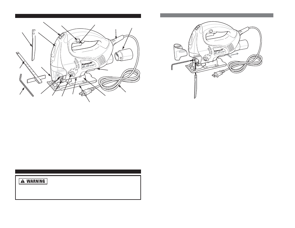
N
C
CO
ON
NT
TR
RO
OL
LS
S A
AN
ND
D C
CO
OM
MP
PO
ON
NE
EN
NT
TS
S::
1. Trigger
2. Trigger Lock
3. Speed Control Adjusting Switch
4. Gear Housing
5. Blade Guard
6. Blade Holder
7. Blade
8. Roller Guide
9. Stroke Adjustment Switch
A
AS
SS
SE
EM
MB
BL
LY
Y
D
Diisscco
on
nn
neecctt p
pllu
ug
g ffrro
om
m A
AC
C p
po
ow
weerr sso
ou
urrccee b
beeffo
orree
aasssseem
mb
blliin
ng
g p
paarrttss,, m
maakkiin
ng
g aad
djju
ussttm
meen
nttss,, o
orr cch
haan
ng
giin
ng
g b
bllaad
deess.. Failure to
remove electrical power could cause accidental starting of the jigsaw resulting
in serious injury to the operator and/or damage to the tool.
10. Bevel Markings
11. Bevel Plate
12. Base Plate
13. Hex Wrench Storage
14. Power Cord
15. Power Cord Strain Relief
16. Vacuum Attachment
17. Hex Wrench
18. Rip Fence Guide
1
16
15
11
12
14
13
10
9
2
3
4
5
6
17
18
8
7