Kawasaki 691295 User Manual
Page 5
FFU
UN
NC
CT
TIIO
ON
NA
AL
L D
DE
ES
SC
CR
RIIP
PT
TIIO
ON
N
C
CO
ON
NT
TR
RO
OL
LS
S A
AN
ND
D C
CO
OM
MP
PO
ON
NE
EN
NT
TS
S::
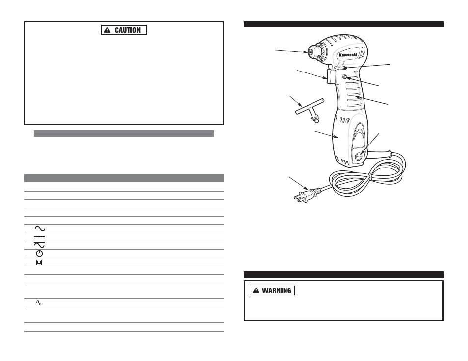
1. Trigger Switch
2. Lock-On Switch
3. Direction Control Lever
4. Comfort Rubber Grip
5. Motor Housing
O
OP
PE
ER
RA
AT
TIIN
NG
G IIN
NS
ST
TR
RU
UC
CT
TIIO
ON
NS
S
D
Diisscco
on
nn
neecctt tth
hee p
po
ow
weerr p
pllu
ug
g ffrro
om
m tth
hee A
AC
C p
po
ow
weerr sso
ou
urrccee
b
beeffo
orree aan
nyy aasssseem
mb
bllyy,, aad
djju
ussttm
meen
nttss,, o
orr aad
dd
diin
ng
g//rreem
mo
ovviin
ng
g aacccceesssso
orriieess..
Following this preventative step reduces the risk of the drill coming on acciden-
tally and the risk of damage to the workpiece and injury to the operator.
8
7
T
To
o p
prreevveen
ntt aacccciid
deen
nttaall ssttaarrttiin
ng
g,, aallw
waayyss d
diisscco
on
nn
neecctt tth
hee p
pllu
ug
g ffrro
om
m tth
hee p
po
ow
weerr
sso
ou
urrccee b
beeffo
orree m
maakkiin
ng
g aan
nyy aad
djju
ussttm
meen
nttss o
orr cch
haan
ng
giin
ng
g aacccceesssso
orriieess..
N
Neevveerr rru
un
n tth
hee d
drriillll w
wh
hiillee ccaarrrryyiin
ng
g iitt aatt yyo
ou
urr ssiid
dee..
IIff tth
hee b
biitt b
beecco
om
meess b
bo
ou
un
nd
d iin
n tth
hee w
wo
orrkk p
piieeccee,, rreelleeaassee tth
hee ttrriig
gg
geerr iim
mm
meed
diiaatteellyy
aan
nd
d p
prreep
paarree ffo
orr tth
hee tto
oo
oll tto
o kkiicckkb
baacckk tto
ow
waarrd
d yyo
ou
u.. Reverse the direction of rota-
tion, then back out the bit by slowly squeezing the trigger.
M
Maakkee ssu
urree aallll aacccceesssso
orriieess aarree rraatteed
d ffo
orr tth
hee rreecco
om
mm
meen
nd
deed
d ssp
peeeed
d o
off tth
hee d
drriillll..
Brushes, grinding wheels and other accessories may fall apart if run at too high
a speed, sending dangerous debris flying at the operator.
U
Ussee g
gllo
ovveess w
wh
heen
n cch
haan
ng
giin
ng
g h
ho
ott b
biittss aan
nd
d aacccceesssso
orriieess tto
o aavvo
oiid
d b
bu
urrn
nss..
S
SY
YM
MB
BO
OL
LS
S
IIM
MP
PO
OR
RT
TA
AN
NT
T:: Some of the following symbols may be used on your tool. Please
study them and learn their meaning. Proper interpretation of these symbols will
allow you to operate the tool better and safer.
S
SY
YM
MB
BO
OL
L
N
NA
AM
ME
E
E
EX
XP
PL
LA
AN
NA
AT
TIIO
ON
N
V
Volts
Voltage (Potential)
A
Amperes
Current
Hz
Hertz
Frequency (Cycles per Second)
W
Watt
Power
Kg
Kilograms
Weight
Alternating Current
Type of Current
Direct Current
Type of Current
Alternating or Direct Current
Type of Current
Earthing Terminal
Grounding Terminal
Class II Construction
Denotes Double Insulation
min
Minutes
Time
s
Seconds
Time
Diameter
Size of Drill Bits,
Grinding Wheels, etc.
No load speed
No-load Rotational Speed
.../min
Revolutions per Minute
Revolutions, Surface Speed,
Strokes, etc. per Minute
1,2,3, …
Ring Selector Settings
Speed, Torque or Position Settings
2
4
6
3
9
5
7
1
8
6. Motor Brush (2)
7. Double Insulated Power Cord
8. Chuck
9. Chuck Key