1 - pcb removal and replacement, Operate. refer to, Section 5.4.1, “pcb removal and – KVH Industries TracVision S2 User Manual
Page 45: Replacement, For details on the fuse location and, 1 pcb removal and replacement
5-4
A Guide to TracVision S2
5.4.1 PCB Removal and Replacement
Estimated Time to Repair:
1
⁄
2
hour
The microprocessor PCB assembly is protected by a cover
fastened to the rotating plate –
removed to gain access to the main power fuse and the PCB
assembly.
1. Using needle-nose pliers, remove the E-ring from
one end of the connecting rod –
2. Remove the connecting rod by sliding it off the
bracket.
3. Fully retract the elevation axis motor shaft
When carrying out maintenance
on the PCB, be sure to not drop
any of the small screws inside the
mechanism. If a screw is lost within
the baseplate, it must be retrieved
to avoid causing any damage when
the unit rotates.
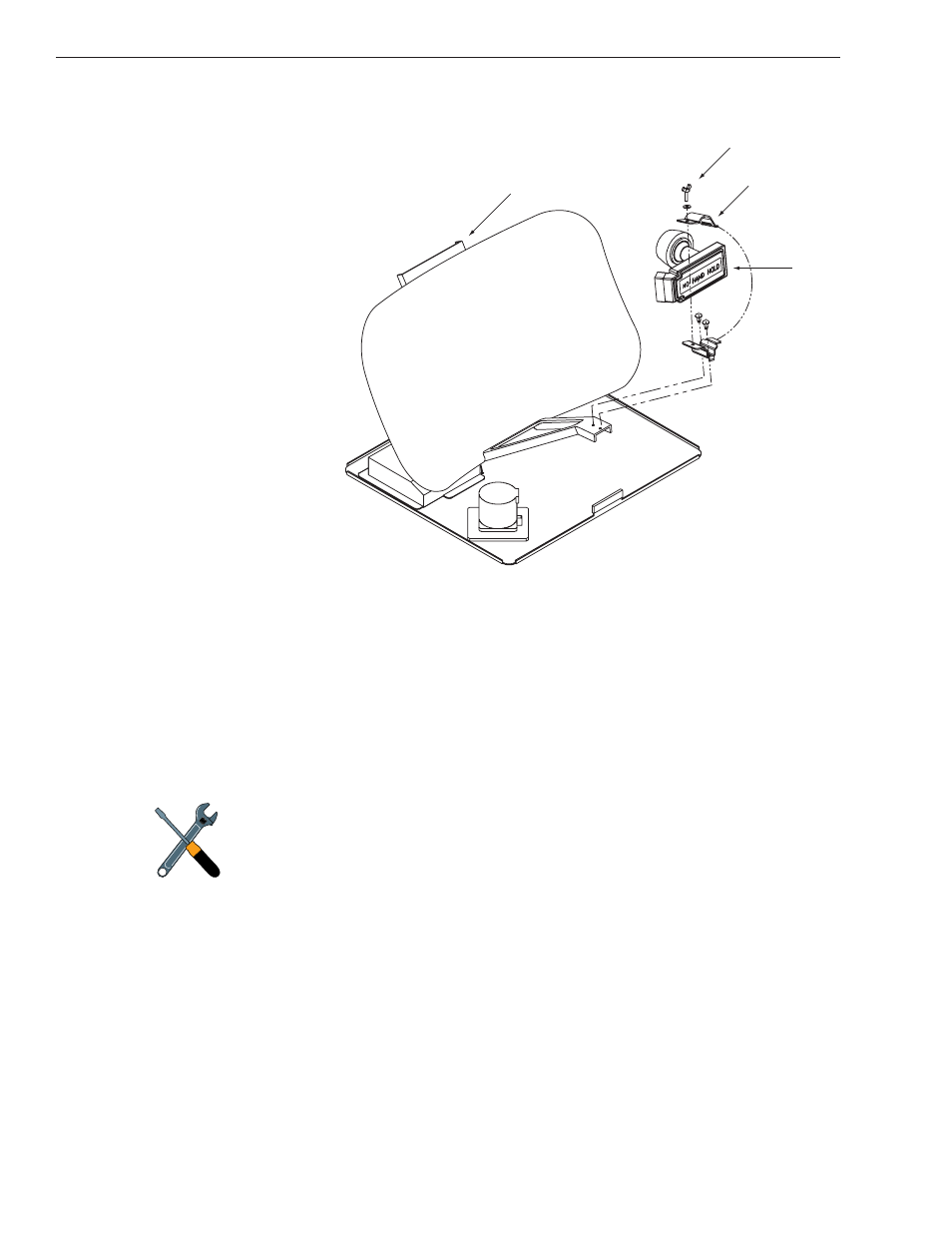
Reflector Bracket
Wing Screw
and Washer
LNB Clamp
LNB
Figure 5-3
Antenna Assembly