Controls, English, Speaker output terminals • stereo connections – Kenwood KAC-PS501F User Manual
Page 4: Bridged connections, This controls the b.m.s. (see p.6), 2 caution
4
English
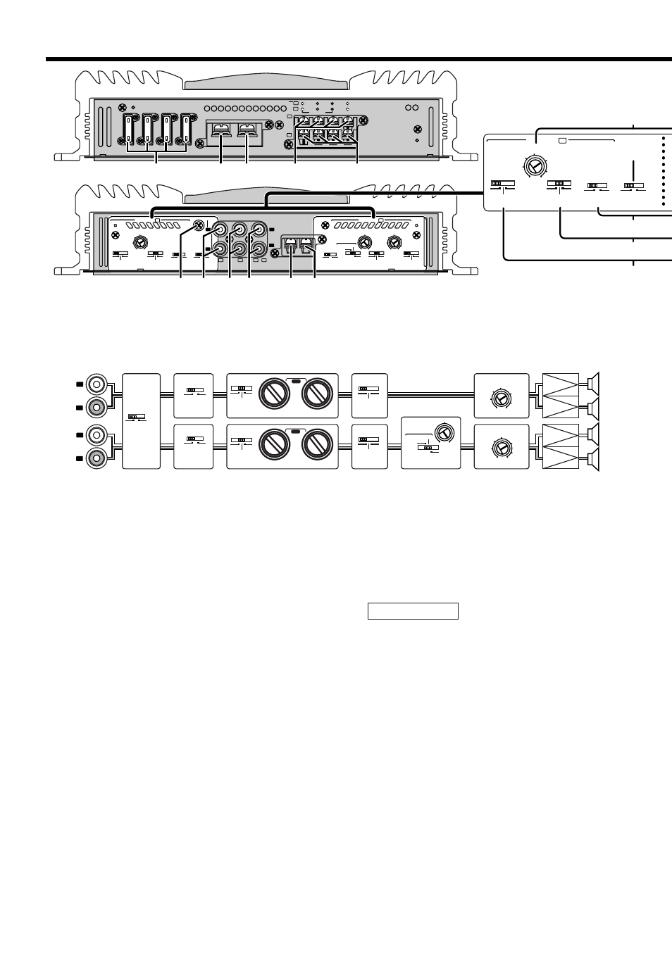
Controls
This is a 4 channel amplifier including 2 stereo amplifiers in a body. One amplifier is referred to
as amplifier A and the other is amplifier B. This unit is compatible with a large variety of
systems by combining the switches and functions described in the following.
L
R
L
R
LINE IN
P.CON
EXT.AMP.CONT.
GND
MONO
LINE OUT
25Hz
15Hz
INFRASONIC
FILTER
OPERATION
OFF
0.2
0.5
5
1
2
3
4
B
B
A
A
+
(MAX)
(MIN)
25Hz
15Hz
INFRASONIC
FREQ (Hz)
FREQ (Hz)
OFF
LPF
OFF
HPF
MONO
STEREO
FILTER
LPF
OFF
HPF
OPERATION
MONO
STEREO
B.M.S.
B.M.S.
FREQ(Hz)
B.M.S.
(
+
6)
CLOSE
OPEN/ B.M.S.
(REMOTE)
INPUT SELECT
A
AB
CONTROL
INPUT SENSITIVITY(V)
0.2
0.5
5
1
2
3
4
100
50
80
(MAX)
(MIN)
INPUT SENSITIVITY(V)
A
CONTROL B
LEFT
BRIDGED
RIGHT
SPEAKER OUTPUT
FUSE(20A
×
4)
BATT.
GND
B
B
A
A
20
20
20
20
$
%
*
@
25Hz
15Hz
INFRASONIC
FILTER
OPERATION
OFF
0.2
0.5
5
1
2
3
4
(MAX)
(MIN)
FREQ (Hz)
LPF
OFF
HPF
MONO
STEREO
INPUT SELECT
A
AB
CONTROL
INPUT SENSITIVITY(V)
A
#
1
4
2 3
7 8 9
6
0 !
5
1
Fuse (20 A
×
4)
2
Battery terminal
3
Ground terminal
4
Amplifier A speaker output
terminals
5
Amplifier B speaker output
terminals
❖
SPEAKER OUTPUT terminals
• Stereo Connections:
When you wish to use the unit as a stereo
amplifier, stereo connections are used.
The speakers to be connected should
have an impedance of 2
Ω
or greater.
When multiple speakers are to be
connected, ensure that the combined
impedance is 2
Ω
or greater for each
channel.
• Bridged Connections:
When you wish to use the unit as a high-
output monaural amplifier, bridged
connections are used. (Make connections
to the LEFT channel (+) and the RIGHT
channel (-) SPEAKER OUTPUT terminals.)
The speakers to be connected should
have an impedance of 4
Ω
or greater.
When multiple speakers are to be
connected, ensure that the combined
impedance is 4
Ω
or greater.
The rated input of the speakers should be
no less than the maximum output of the
amplifier. Otherwise malfunction may
result.
6
RCA cable ground lead terminal
7
Amplifier A LINE IN terminal
8
Amplifier B LINE IN terminal
9
LINE OUT terminal
These jacks output respectively the signals
input to amplifiers A and B. They always
output the stereo signals regardless of the
position of the OPERATION switch.
0
Power control terminal
!
EXT.AMP.CONT. (external
amplifier control) terminal
This controls the B.M.S. (See P.6).
2CAUTION
L
R
L
R
A
B
LO PASS
50
50
200
200
HI PASS
LO PASS
50
50
200
200
HI PASS
A
B
25Hz
15Hz
INFRASONIC
FILTER
OPERATION
OFF
25Hz
15Hz
INFRASONIC
FREQ (Hz)
FREQ (Hz)
OFF
LPF
OFF
HPF
MONO
STEREO
FILTER
LPF
OFF
HPF
OPERATION
MONO
STEREO
INPUT SELECT
A
AB
0.2
0.5
5
1
2
3
4
(MAX)
(MIN)
INPUT SENSITIVITY(V)
0.2
0.5
5
1
2
3
4
(MAX)
(MIN)
INPUT SENSITIVITY(V)
@
#
$
%
&
^
*
#1
#2
B.M.S.
B.M.S.
FREQ(Hz)
B.M.S.
(
+
6)
CLOSE
OPEN/ B.M.S.
(REMOTE)
100
50
80
#1 When FILTER is set to LPF, the sound is monaural (L+R).
#2 When INFRASONIC is set to 15Hz or 25Hz, the sound is monaural (L+R).
* Note that if OPERATION is set to MONO, Lch is still monaural.
Block diagram