Kawasaki RH1-090048 User Manual
Page 35
A
AT
TT
TA
AC
CH
HIIN
NG
G T
TH
HE
E B
BL
LA
AD
DE
E::
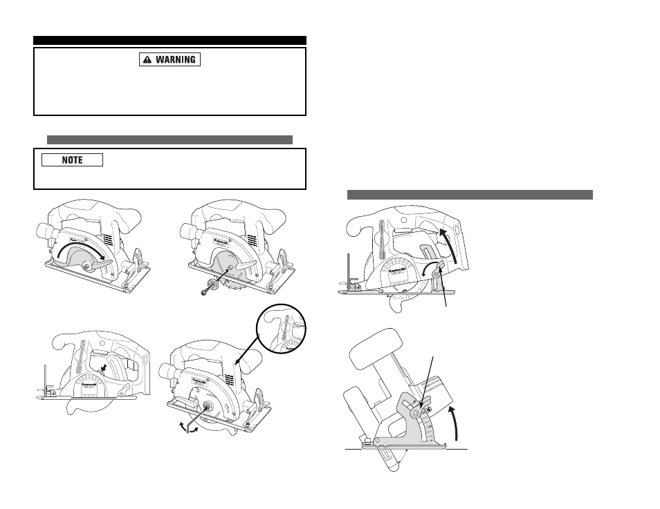
1. Remove the battery pack.
2. Retract the lower guard (see Fig. 1).
3. Slip the blade into place (see Fig. 2).
4. Put clamp washers and clamping
screw loosely in position.
5. Use the wrench to tighten the
clamping screw while pressing
down on the clamping knob
(see Fig. 3 and Fig. 4).
6. Remove wrench.
7. Replace the battery pack.
A
AD
DJJU
US
ST
TIIN
NG
G D
DE
EP
PT
TH
H A
AN
ND
D A
AN
NG
GL
LE
E
A
AD
DJJU
US
ST
T C
CU
UT
TT
TIIN
NG
G D
DE
EP
PT
TH
H::
1. Remove the battery pack.
2. Hold the saw firmly and loosen the
depth adjustment knob by turning
it counter-clockwise.
3. Move the shoe to obtain the desired
depth of cut.
4. Tighten depth adjustment knob
securely by turning clockwise
before operating the saw.
A
AD
DJJU
US
ST
T B
BE
EV
VE
EL
L A
AN
NG
GL
LE
E::
1. Remove the battery pack.
2. Loosen the bevel angle knob by
turning it counter-clockwise.
3. Adjust the angle of your cut.
4. Tighten the angle knob securely
by turning clockwise.
15
A
AS
SS
SE
EM
MB
BL
LY
Y
A
Allw
waayyss rreem
mo
ovvee b
baatttteerryy p
paacckk b
beeffo
orree iin
nssttaalllliin
ng
g o
orr rreem
mo
ovviin
ng
g b
bllaad
dee..
W
Wh
heen
n rreem
mo
ovviin
ng
g tth
hee b
bllaad
dee ffrro
om
m tth
hee tto
oo
oll,, aavvo
oiid
d cco
on
nttaacctt w
wiitth
h sskkiin
n aan
nd
d u
ussee
p
prro
op
peerr p
prro
otteeccttiivvee g
gllo
ovveess w
wh
heen
n g
grraassp
piin
ng
g tth
hee b
bllaad
dee o
orr aacccceesssso
orryy.. Accessories
may be hot after prolonged use.
A
AT
TT
TA
AC
CH
HIIN
NG
G // R
RE
EM
MO
OV
VIIN
NG
G B
BL
LA
AD
DE
E
If the blade clamp screw will not loosen enough to allow
blade installation, tap gently on the end of the wrench with a mallet until the
clamp screw breaks free.
R
RE
EM
MO
OV
VIIN
NG
G T
TH
HE
E B
BL
LA
AD
DE
E::
1. Remove the battery pack.
2. Use the wrench to loosen the
clamping screw while pressing
down on the blade safety lock
button (see Fig. 3 and Fig. 4).
3. Remove the blade.
4. Tighten the blade clamp
screw back into place.
5. Remove wrench.
6. Replace the battery pack.
FIG. 1
FIG. 3
FIG. 4
FIG. 2
L
LO
OO
OS
SE
EN
N::
CLOCKWISE
T
TIIG
GH
HT
TE
EN
N::
COUNTER-CLOCKWISE
30º
DEPTH ADJUSTMENT
KNOB
BEVEL ANGLE KNOB
16