Klaxon Syrex IS-XN User Manual
Page 3
_______________________________________________________________________________________________________________________________
Klaxon Signals Ltd.
Wrigley Street, Oldham, Lancashire UK OL4 1HW [email protected] Tel: +44 (0)161 287 5555
www.klaxonsignals.com Fax: +44 (0)161 287 5511
Document No. Klaxon Syrex IS-XN Issue: A 11-11-05 Sheet 3 of 3
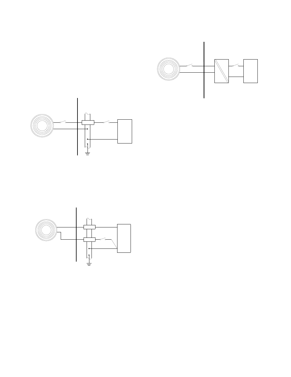
6. ELECTRICAL SYSTEM DESIGN FOR INSTALLATION IN
HAZARDOUS AREAS USING ZENER BARRIERS
If the beacon is controlled by a switch in the positive supply,
or the power supply is being turned on and off, only a single
channel Zener barrier is required as shown in Fig 3. This
circuit may also be used if the beacon is being controlled by a
mechanically activated switch on the hazardous area side of
the barrier. The power supply voltage should be between 20V
and the maximum working voltage of the barrier. The circuit
will continue to work at lower voltages, but the beacon light
output level will be reduced.
If the beacon is being operated from a lower voltage power
supply of say 12V or less, then a 15V 100 ohm barrier can be
used which will improve the beacon light output levels at
lower voltages.
Power
Supply
+
0V
Barrier
On/Off
+
-
28V 1.2W
Positive
Hazardous Area
Safe Area
Syrex IS-XN
Beacon
Fig 3 Using a single channel barrier.
If the beacon control switch is in the negative wire and the
power supply 0V is earthed, the circuit shown in Fig 4 may be
used. For simplicity the two barriers may be combined into
one package. The power supply voltage should be between
21V and the maximum working voltage of the 28V barrier.
The circuit will continue to work at lower voltages, but the
beacon brilliance will be reduced.
Power
Supply
+
0V
Barrier
28V 1.2W
Positive
Hazardous Area
Safe Area
Diode Return
Barrier
On/Off
+
-
Syrex IS-XN
Beacon
Fig 4 Single stage alarm using two channel barrier.
7. ELECTRICAL SYSTEM DESIGN FOR INSTALLATION IN
HAZARDOUS AREAS USING GALVANIC ISOLATORS.
Galvanic isolators do not require a high integrity earth
connection. For small systems where a high integrity earth is
not already available, the use of galvanic isolators often
reduces the overall installation cost and simplifies design.
The Syrex IS-XN beacon may be powered by any galvanic
isolator having output parameters within the limits specified in
section 4.3, which has been certified EEx ia by an EC
Notified Body. The beacon may be controlled by turning
the galvanic isolator on and off, or by a mechanically
activated switch on the hazardous area side of the isolator.
Power
Supply
+
0V
+
-
Hazardous Area
Safe Area
-
+
Galvanic
Isolator
On / Off
Klaxon IS-XN
Beacon
Fig 5 Basic circuit for use with a galvanic isolator.
The control arrangement will vary depending upon the
isolator chosen. The galvanic isolator must be able to supply
an output of 30mA at about 16V.
10. CABLE PARAMETERS
The maximum permitted cable parameters are as specified
on the certificate of the Zener barrier or galvanic isolator that
has been selected for the installation. Normally the limits are
not restrictive, but care should be taken not to exceed a
capacitive limit of 83nF for IIC installations when very long
cables are used.
11. BEACON FLASH RATE
The Syrex IS-XN can be set to two flash rates 1 double flash
per second 1Hz (slow rate) or two double flashes per second
2Hz fast rate).
The flash rate is selected by the position of the pin header
next to the input terminal block (see fig 1).
12. MAINTENANCE
The beacon should be regularly inspected to ensure that it
has not been damaged. Frequency of inspection depends
upon environmental conditions, but initially we recommend
that this should be done annually.
No attempt should be made to repair a faulty Syrex IS-XN
beacon. Suspect beacons must be returned to Klaxon
Signals Ltd. or to your local agent for repair
.
13. GUARANTEE
Beacons which fail within the guarantee period should be
returned to Klaxon Signals Ltd. or our local agent. It is helpful
if a brief description of the fault symptoms is provided.