Installation, Before starting: overview, Dimensions – SECO-LARM USA 84-IR LED Bullet Cameras EV-1826-PKGQ User Manual
Page 3
ENFORCER Zeta Series 84-IR LED Bullet Cameras
SECO-LARM U.S.A., Inc. 3
1. Run a 12VDC power supply wire and a video cable
with a male BNC connector through the wall to where
the camera is to be mounted.
2. Temporarily connect the camera to the 12VDC power
supply. Do not cut the DC jack or female BNC plug
as warranty will be voided. If needed, use the
included SECO-LARM DC plug with
terminal block.
3. Temporarily connect the camera’s female BNC jack to
the video cable’s male BNC plug. While watching the
monitor, hold the camera bracket by hand against the
wall where it is to be mounted, then twist the camera
until it is certain that this mounting location is correct.
Use a pencil to mark the location of the four screw
holes in the bracket.
4. Disconnect the 12VDC power supply and video cable.
Installation:
5. Mount the bracket to the wall using the four included
mounting screws.
6. If mounting to the EV-11LR or EV-11LS, see instructions
on page 2.
7. Reconnect the 12VDC power supply and video cable.
Turn the monitor on and make sure the camera is
sending the proper video signal.
8. Use the OSD controller (sold separately) or in-line OSD
joystick to adjust camera settings (see the separate
OSD manual).
9. To adjust the camera angle, loosen and tighten the
adjustment nut, or loosen and tighten either of the two
screws on the mounting arm.
10. Adjust the zoom and focus using the included hex
wrench.
11. Do a final test of the video camera and monitor.
1. Please read this manual carefully and keep it for
future reference.
2. Use the camera within given temperature and
electrical limits.
3. Do not aim the LED light directly at the eyes when the
LEDs are on.
4. Do not point the camera at the sun. Heat could damage
the camera, even when not in use.
5. Do not mount the camera in areas exposed to
radiation, strong magnetic fields, or strong electrical
signals.
6. Do not open or disassemble the camera. There are
no field serviceable parts inside.
7. Do not drop the camera or subject it to strong
vibrations.
Before Starting:
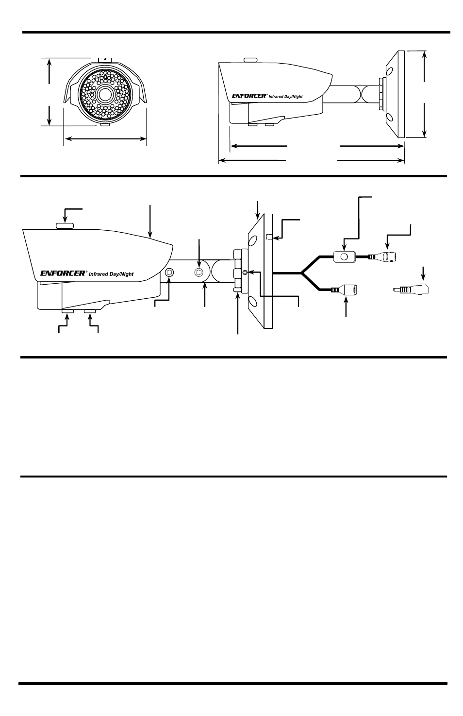
Overview:
Sunshield
Mounting arm
adjustment screw
Mounting base
Surface mount
knock-out
Remove with a pair of
pliers
Adjustment
screw
Adjustment nut
Mounting
arm
Camera angle
adjustment screw
Zoom
Focus
Female BNC connector
DC Jack
Sunshield
screw
Dimensions:
10
1
/
4
” (260mm)
10
13
/
16
” (275mm)
4
5
/
8
”
(118mm)
DC Plug with
terminal block
In-line OSD joystick*
*Optional Zeta Series OSD controller available for
added convenience. (Model #: EV-18C)
4
5
/
8
” (116mm)
4
5
/
16
”
(109mm)