Caution – Scag Power Equipment STWC61V-25KA-LC User Manual
Page 27
23
R
Section 6
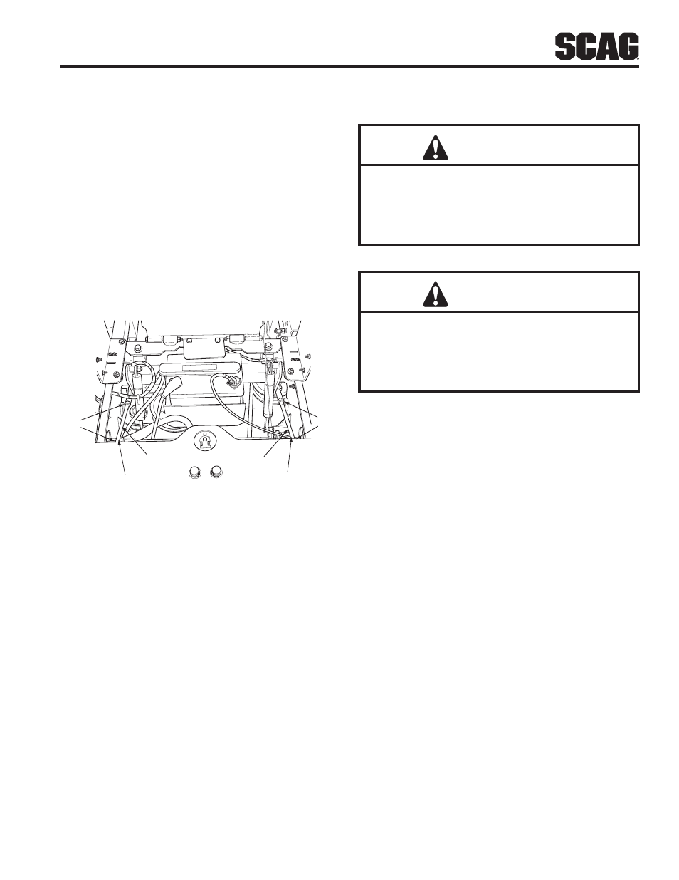
NEUTRAL ADJUSTMENT
Be sure the dump valve levers are in the run position
1.
and the steering control levers are in the neutral lock
position.
With an operator in the seat, start the engine and
2.
disengage the parking brake.
Run the engine at full operating speed and check if
3.
the machine creeps forward or backwards.
Adjust the RH wheel by loosening the jam nuts on
4.
the steering control rod and turning the rod until the
drive wheel turns in the forward direction. Turn the
rod back until the drive wheel stops moving. Turn the
rod an additional 1/2 turn. See Figure 6-3.
ADJUST
HERE
ADJUST
HERE
JAM
NUTS
STC2002SCRA
LEFT STEERING
CONTROL ROD
RIGHT STEERING
CONTROL ROD
JAM
NUTS
Steering Control Rod Adjustment
Figure 6-3.
Tighten the jam nuts and repeat for the LH wheel.
5.
See Figure 6-3.
Actuate the steering control levers forward and
6.
reverse several times and return them to the neutral
position.
Check that the drive wheels remained in neutral and
7.
readjust if necessary.
Check that the steering control levers hit the stop
8.
before the pumps reach full stroke. Adjust as
needed.
TRACKING ADJUSTMENT
CAUTION
Stop the engine and remove the key from the
ignition before making any adjustments. Wait
for all moving parts to come to a complete stop
before beginning work.
CAUTION
The engine and drive unit can get hot during
operation causing burn injuries. Allow engine
and drive components to cool before making any
adjustments.
- NOTe -
Before proceeding with this adjustment, be sure
that the caster wheels turn plus pivot freely and
that the tire pressure in the drive wheels is correct.
If the tire pressure is not correct, the machine will
pull to the side with the lower pressure.
If at full speed the mower pulls right, it is an
1.
indication that the left wheel is turning faster than
the right wheel. To adjust this condition, proceed as
follows:
A. Stop the machine and place the steering control
levers in the neutral position. Loosen the lock nuts
securing the ball joints at each end of the LH steering
control rod. Rotate the control rod to lengthen the rod
and tighten the lock nuts. This will cause the control
rod to stroke the LH pump less, slowing down the LH
wheel. See Figure 6-3.
- NOTe -
If after making the adjustment as outlined in step
1A, the machine creeps forward or backward,
perform the neutral adjustment. See Neutral
Adjustment above.