Silicon Laboratories C8051F04X-DK User Manual
Kit contents, Hardware setup using a usb debug adapter, S e r
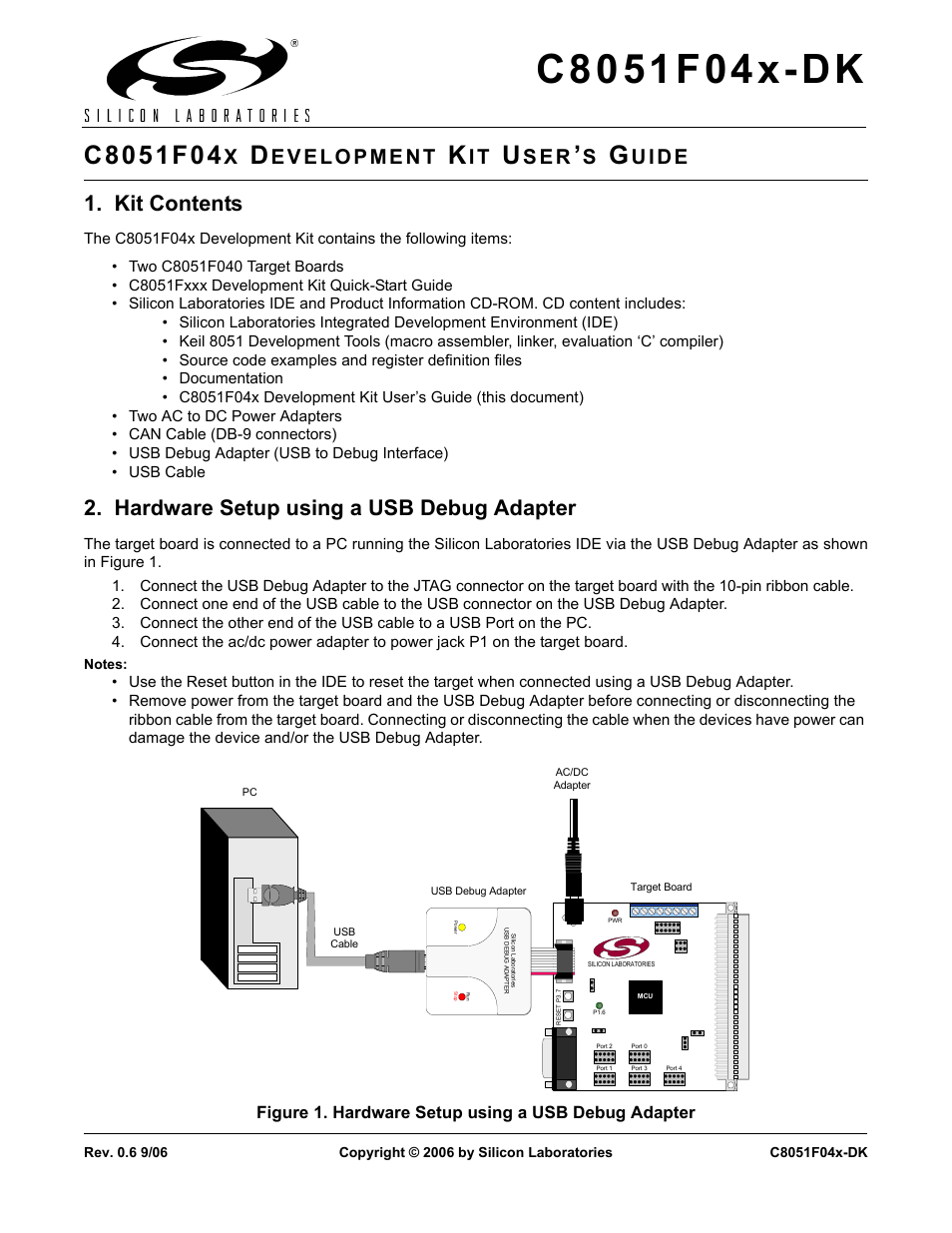
Table of contents
Document Outline
- 1. Kit Contents
- 2. Hardware Setup using a USB Debug Adapter
- 3. Software Setup
- 4. Silicon Laboratories Integrated Development Environment
- 5. Example Source Code
- 6. Target Board
- Figure 3. C8051F040 Target Board
- 6.1. System Clock Sources
- 6.2. Switches and LEDs
- 6.3. Target Board JTAG Interface (J4)
- 6.4. Serial Interface (J5)
- 6.5. Analog I/O (J11, J20)
- 6.6. Controller Area Network (CAN) Interface (J25)
- 6.7. PORT I/O Connectors (J12 - J19)
- 6.8. VDD Monitor Disable (J23)
- 6.9. Expansion I/O Connector (J24)
- 6.10. VREF Connector (J22)
- 7. Schematic
- Document Change List
- Contact Information