Figure 1: sample application installation, Also available from seco-larm – SECO-LARM USA Enforcer Video EVT-PB1-H05Q User Manual
Page 3
ENFORCER Video, Power and Data Balun with Voltage Booster
SECO-LARM U.S.A., Inc 3
SECO-LARM U.S.A., Inc.
33 3
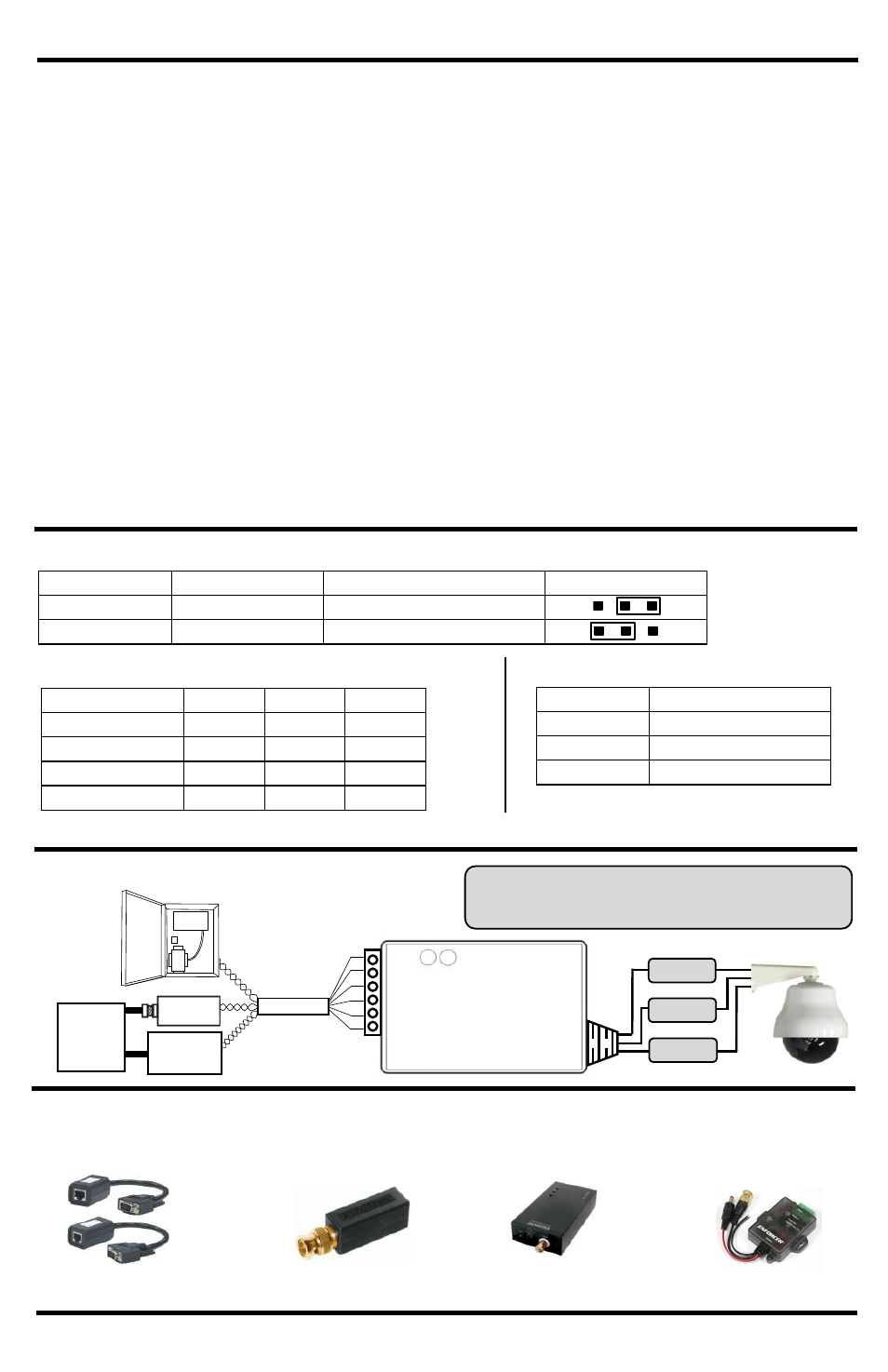
Figure 1: Sample Application
Installation:
1. Run UTP cable to the camera where the VPD balun is being installed.
2. Remove the cover by simultaneously pressing down on the top cover, and lifting up on the side
mounting tabs. This will release the tight seal between the top and bottom covers.
3. Set the desired output voltage using the selection jumper according to table 1 below.
4. Connect output wires from the power supply to the power input terminal blocks on the balun.
Observe correct polarity
5. Apply power and use table 2 and 3 below to check the status of the input and output voltages.
NOTE: To avoid potential damage, use a voltage meter to ensure proper voltage is
present at the input and output terminal blocks. Observe correct polarity.
6. Connect the camera to the DC plug on the balun. If the output voltage is too low, then turn the
rotary knob clockwise to increase the voltage or counter-clockwise to decrease the voltage.
7. Connect the video input male BNC input in from the VPD Balun to the camera.
8. If using a RS-485 controlled camera, connect the data in wires to the camera.
9. Using the input terminal blocks, connect data and video wires to the balun according to Figure 1.
IMPORTANT: Correct polarity must be observed on all connections.
10. Replace the cover on the voltage booster.
Table 1: Adjustable Output Voltage
Table 2: Wiring Distance 12 VDC Voltage Drop
NOTE: To avoid potential damage, use a voltage meter to
ensure proper voltage is present at the input and output
terminal blocks. Observe correct polarity.
Input Voltage
Output Voltage
Adjustable voltage range Jumper Settings
7~12VDC
12VDC
12.5 ±
5%VDC
12~24VDC
24VDC
24.0 ± 10%VDC
24 AWG Wire
1 Pair
2 Pairs 3 Pairs
250mA
90'
220'
550'
500mA
45'
110'
285'
750mA
30'
75'
190'
1A
20'
55'
140'
NOTE: Chart is based on standard Cat5 24AWG wire and an allowable 10% voltage drop.
LED colors
Status
Green
Power is connected
Red
Output is 12VDC
Blue
Output is 24VDC
Table 3: LED Indicators
Also Available from SECO-LARM:
Passive VGA Balun
Passive & Active
Video Baluns
EVT-PB1Q
EVT-SBP-GQ
VPD Balun with
Voltage Booster
VC-1BAQ
BNC-to-VGA
Converter
(shown)
Data out
Video in
VDC out
SECO-LARM
Video Balun
DVR
PTZ
Controller
Cat5 cable
Power
Supply
EVT-PB1-H05Q