Datasheet – SMSC USB20H04 User Manual
Page 10
4-Port USB 2.0 Hub Controller
Datasheet
Revision 1.63 (03-30-07)
Page 10
SMSC USB20H04
DATASHEET
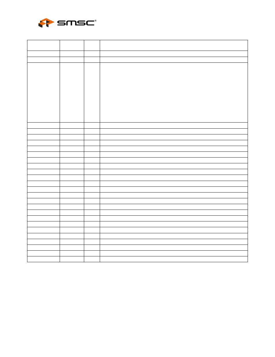
Table 4.3 - USB I/O Signals
NAME
BUFFER
TYPE
ACTIVE
LEVEL
DESCRIPTION
USBDP0 IO-U
N/A
Upstream
USB Positive Data Pin.
USBDM0
IO-U
N/A
Upstream USB Negative Data Pin.
VBUSDET IO8
N/A
Detects state of upstream V
BUS
power. When designing a detachable
hub, this pin must be connected to the V
BUS
power pin of the USB port
that is upstream of the hub.
For self-powered applications with a permanently attached upstream
host, this pin must be connected to either 3.3V or 5.0V (typically
VDD3.3).
The USB20H04 monitors VBUSDET to determine when to assert the
internal D+ pull-up resistor (signaling a connect event). When using the
SRP feature, it is necessary to add a 100k ohm resistor from this pin to
VSS in order to properly dissipate the upstream V
BUS
Pulse (pulsed with
an 8mA drive capability).
USBDP1
IO-U
N/A
USB Positive Data Pin to downstream port 1.
USBDM1
IO-U
N/A
USB Negative Data Pin to downstream port 1.
VBUS1_N
O8
Low
Enables power to downstream port 1.
OCS1_N
IPU
Low
Over-Current Sense input. Internal pull-up resistor to 3.3V.
GR1_N
OD8
Low
Enables green indicator to downstream port 1.
AM1_N
OD8
Low
Enables amber indicator to downstream port 1.
USBDP2
IO-U
N/A
USB Positive Data Pin to downstream port 2.
USBDM2
IO-U
N/A
USB Negative Data Pin to downstream port 2.
VBUS2_N
O8
Low
Enables power to downstream port 2.
OCS2_N
IPU
Low
Over-Current Sense input. Internal pull-up resistor to 3.3V.
GR2_N
OD8
Low
Enables green indicator to downstream port 2.
AM2_N
OD8
Low
Enables amber indicator to downstream port 2.
USBDP3
IO-U
N/A
USB Positive Data Pin to downstream port 3.
USBDM3
IO-U
N/A
USB Negative Data Pin to downstream port 3.
VBUS3_N
O8
Low
Enables power to downstream port 3.
OCS3_N
IPU
Low
Over-Current Sense input. Internal pull-up resistor to 3.3V.
GR3_N
OD8
Low
Enables green indicator to downstream port 3.
AM3_N
OD8
Low
Enables amber indicator to downstream port 3.
USBDP4
IO-U
N/A
USB Positive Data Pin to downstream port 4.
USBDM4
IO-U
N/A
USB Negative Data Pin to downstream port 4.
VBUS4_N
O8
Low
Enables power to downstream port 4.
OCS4_N
IPU
Low
Over-Current Sense input. Internal pull-up resistor to 3.3V.
GR4_N
OD8
Low
Enables green indicator to downstream port 4.
AM4_N
OD8
Low
Enables amber indicator to downstream port 4.