6 jumper settings, Explanation of jumpers, Glan enable/disable – SUPER MICRO Computer I2DMR-8G2 User Manual
Page 39: Cmos clear
Chapter 2: Installation
2-19
2-6
Jumper Settings
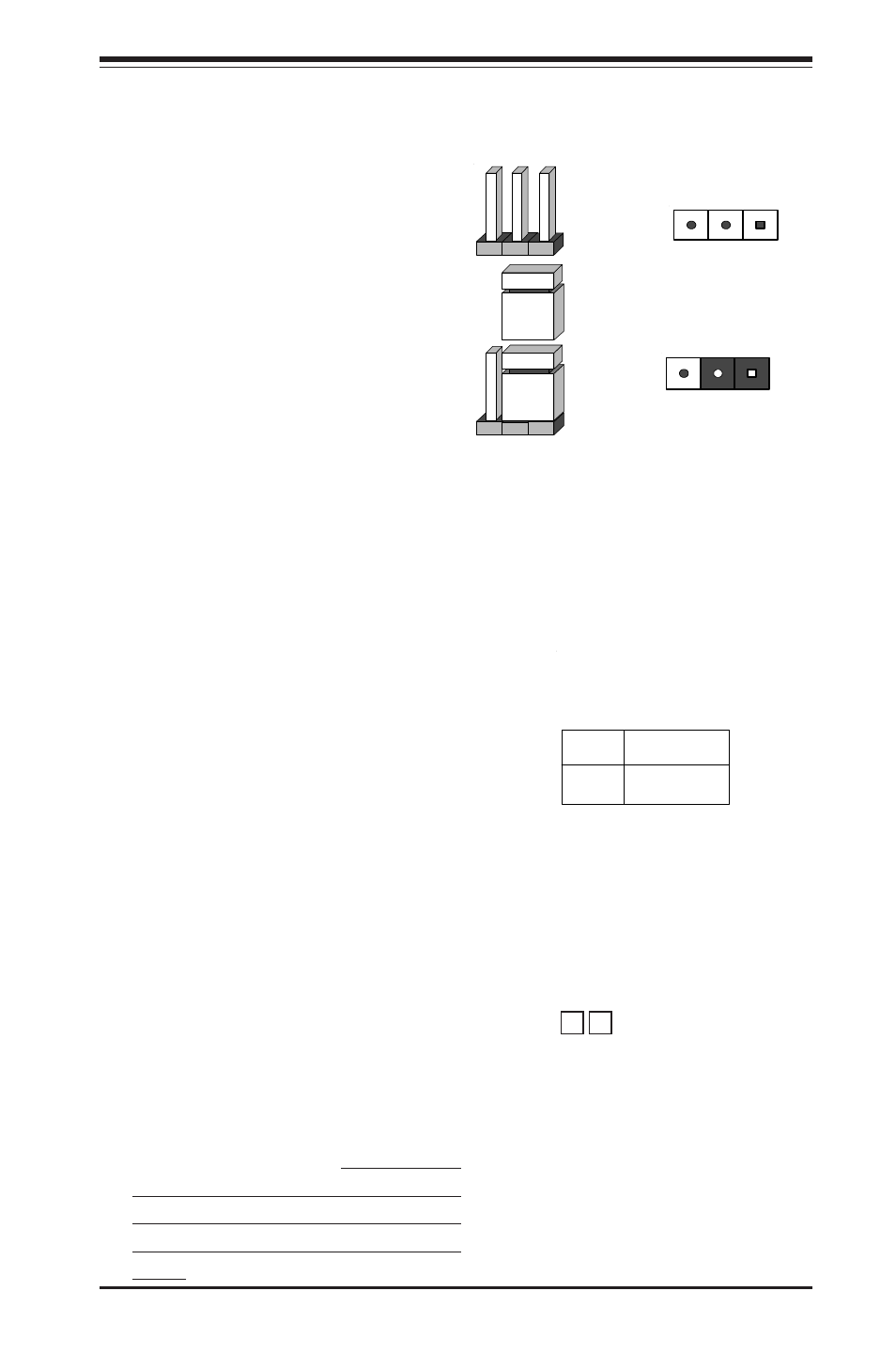
Explanation of
Jumpers
To modify the operation of the
motherboard, jumpers can be
u s e d t o c h o o s e b e t w e e n
o p t i o n a l s e t t i n g s . J u m p e r s
create shorts between two pins
to change the function of the
connector. Pin 1 is identified
w i t h a s q u a r e s o l d e r p a d o n
the printed circuit board. See
the motherboard layout pages
for jumper locations.
N o t e : O n t w o p i n j u m p e r s ,
"Closed" means the jumper is
o n a n d " O p e n " m e a n s t h e
jumper is off the pins.
Connector
Pins
Jumper
Cap
Setting
Pin 1-2 short
3 2 1
3 2 1
GLAN Enable/Disable
J7 enables or disables the GLAN
port(s) on the motherboard. See
the table on the right for jumper
settings. The default setting is
enabled.
Jumper
Position
Pins 1-2
Pins 2-3
Definition
Enabled
Disabled
GLAN
Enable/Disable
Jumper Settings
(J7)
CMOS Clear
JBT1 is not literally a jumper but con-
sists of two contact pads. To clear
the contents of CMOS, short these
pads together by touching them both
with a metal conductor such as the
head of a small screwdriver. JBT1 is
located between the FPUSB4/5(J21)
and Chassis Intrusion(J25) headers
on the motherboard. For ATX/SSI
power supplies, you must completely
shut down the system and remove
the AC power cord before clearing
CMOS.
JBT1