5 of 20, Ts2000 system options - schematic – Security Systems TS2000 User Manual
Page 5
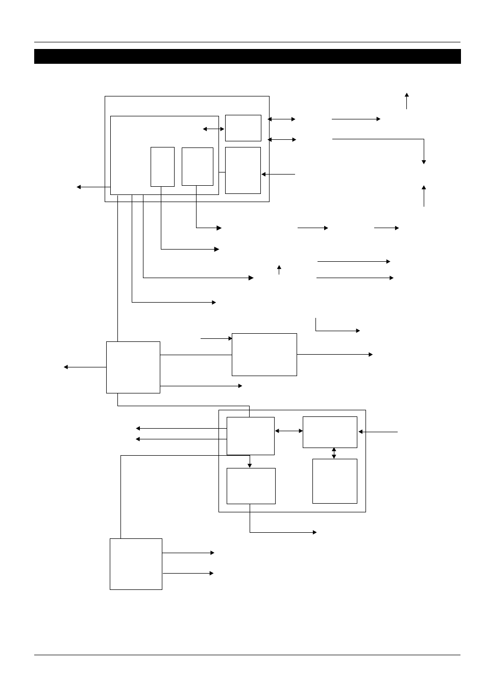
TS2000 System Options - Schematic
496529 Issue A
5 of 20
TS2000
TS2000
SIB*
PIB*
PSU
DC3(M)*
OR D 3*
C P MAIN BOARD
8 Programmable
outputs
DC 28
Digicom
PSTN Line
Central
Station
Mains Input
To PSTN
To PSTN
Approved
Modem
P.C.
To Serial Printer*
8 Outputs*
8 Outputs*
CPA6.OM Unit*
CPA6.OM Unit*
Other outputs:
Wlk Test, Tamp, Aux, Relay,
Sw12, Strobe
12V supply
Loudspeaker
Drive LSD1*
Three Outputs
NODE
UNIT
Four Circuits
Network
Cable
*NODE
UNIT
PSU
Battery
*Relay Unit
RM.3A
Two sets relay
clean contact
Four Circuits
Four Outputs
REM
Mains Input
Bell (SAB1)
Sounder (ES )
PSU Type 150*
Loudspeaker*
(Min impedance 8R)
One Circuit**
Two Outputs**
Network
Cable
2000
CONTROL
PANEL
To Epson*
Printer
Network
Cable
* = Option
** = Other Circuits & Outputs
used for PSU monitoring
and relay drive.
Ward Control Unit option not shown
C
TS
1
Figure 2. TS2000 System Options - Schematic