Ssd-c, I)-3600 d, Table 21: card information structure (continued) – Silicon Image SiliconDrive SSD-C08G(I)-3600 User Manual
Page 38
A
TTRIBUTE
M
EMORY
D
ESCRIPTION
AND
O
PERATION
SSD-C
XXX
(I)-3600 D
ATA
S
HEET
S
ILICON
S
YSTEMS
P
ROPRIETARY
This document and the information contained within it is confidential and proprietary to SiliconSystems, Inc.
All unauthorized use and/or reproduction is prohibited.
3600C-04DSR
P
AGE
28
F
EBRUARY
2, 2009
70h
00h
I
D
IR IQ
T
P
-
Memory-mapped I/O configuration
•
I = 0: No interface byte
•
D = 0: No default entry
•
Configuration index = 0
Configuration table
index byte
TPCE_INDX
72h
01h
M MS IR IO
T
P
-
•
M = 0: No miscellaneous information
•
MS = 00: No memory space
information
•
IR = 0: No interrupt information
present
•
IO = 0: No I/O port information
present
•
T = 0: No timing information present
•
P = 1: V
CC
only information
Feature selection
byte
TPCE_FS
74h
21h
R
DI
PI
AI
SI
HV/LV/NV Nominal voltage only follows
•
R: Reserved
•
DI: Powerdown current information
•
PI: Peak current information
•
AI: Average current information
•
SI: Static current information
•
HV: Maximum voltage information
•
LV: Minimum voltage information
•
NV: Nominal voltage information
Power parameters
for V
CC
76h
B5h
X
Mantissa
Exponent
Nominal voltage = 3.0 V
V
CC
nominal value
78h
1Eh
Extension
+0.3 V
Extension byte
7Ah
4Dh
X
Mantissa
Exponent
Maximum average current over 10ms is
45 mA
Maximum average
current
7Ch
1Bh
CISTPL_TABLE_ENTRY
Configuration table entry tuple
Tuple code
7Eh
0Dh
TPL_LINK
Link length is 10 bytes
Link to next tuple
80h
C1h
I
D Configuration
INDEX
Contiguous I/O mapped ATA registers
configuration
•
I = 1: Interface byte follows
•
D = 1: Default entry
•
Configuration index = 1
Configuration table
index byte
TPCE_INDX
82h
41h
W
R
P
B
Interface Type •
W = 0: Wait not used
•
R = 1: Ready active
•
P = 0: WP not used
•
B = 0: BVS1 and BVD2 not used
•
IF type = 1: I/O interface
Interface description
field TPCE_IF
84h
99h
M MS IR IO
T
P
-
•
M = 1: Miscellaneous information
present
•
MS = 00: No memory space
information
•
IR = 1: Interrupt information present
•
IO = 1: I/O port information present
•
T = 0: No timing information present
•
P = 1: V
CC
only information
Feature selection
byte TPCE_FS
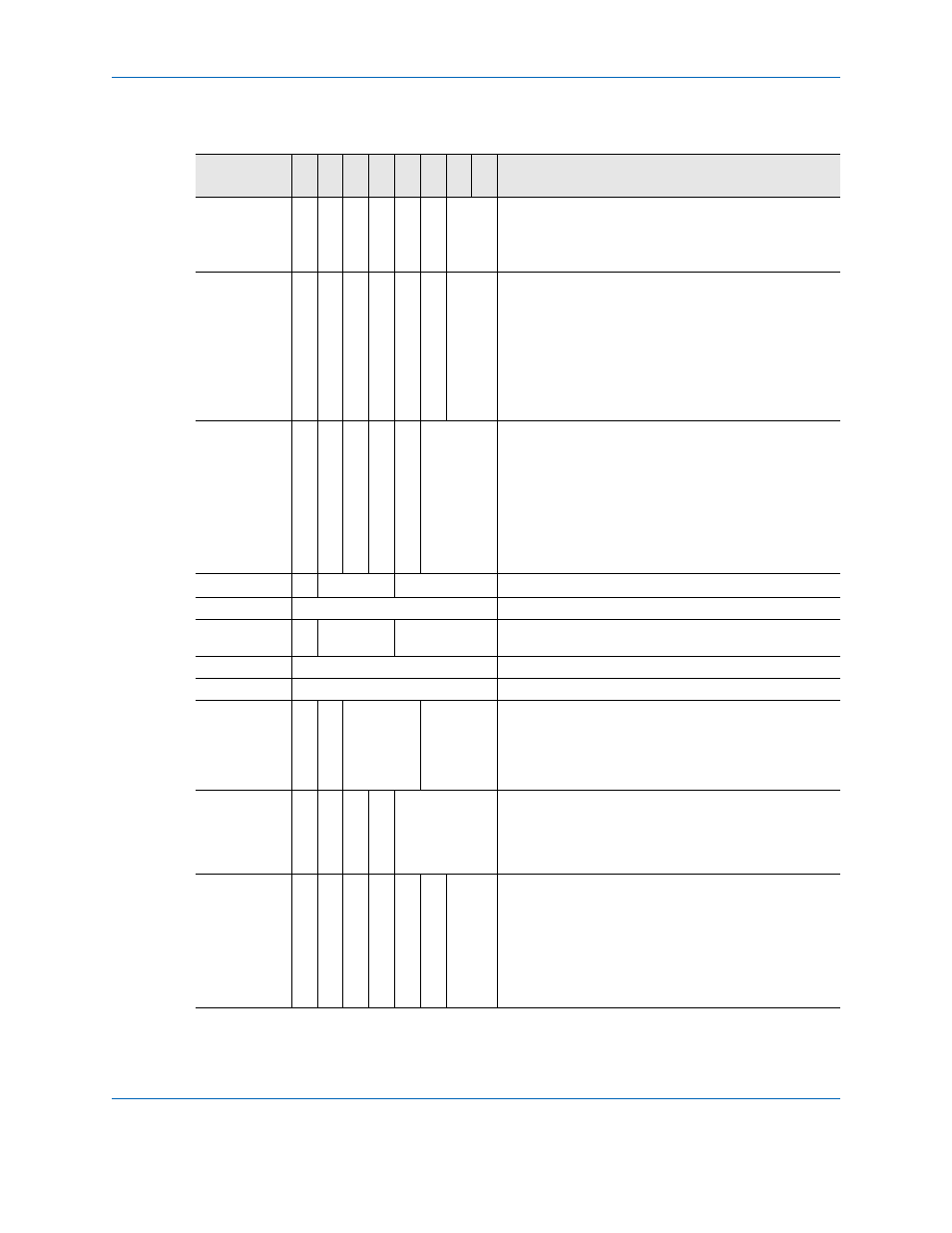
Table 21: Card Information Structure (Continued)
Attribute
Offset
Data 7
6
5
4
3
2
1
0 Description of Contents
CIS Function