Maintenance (continued) – Shindaiwa 89302 User Manual
Page 16
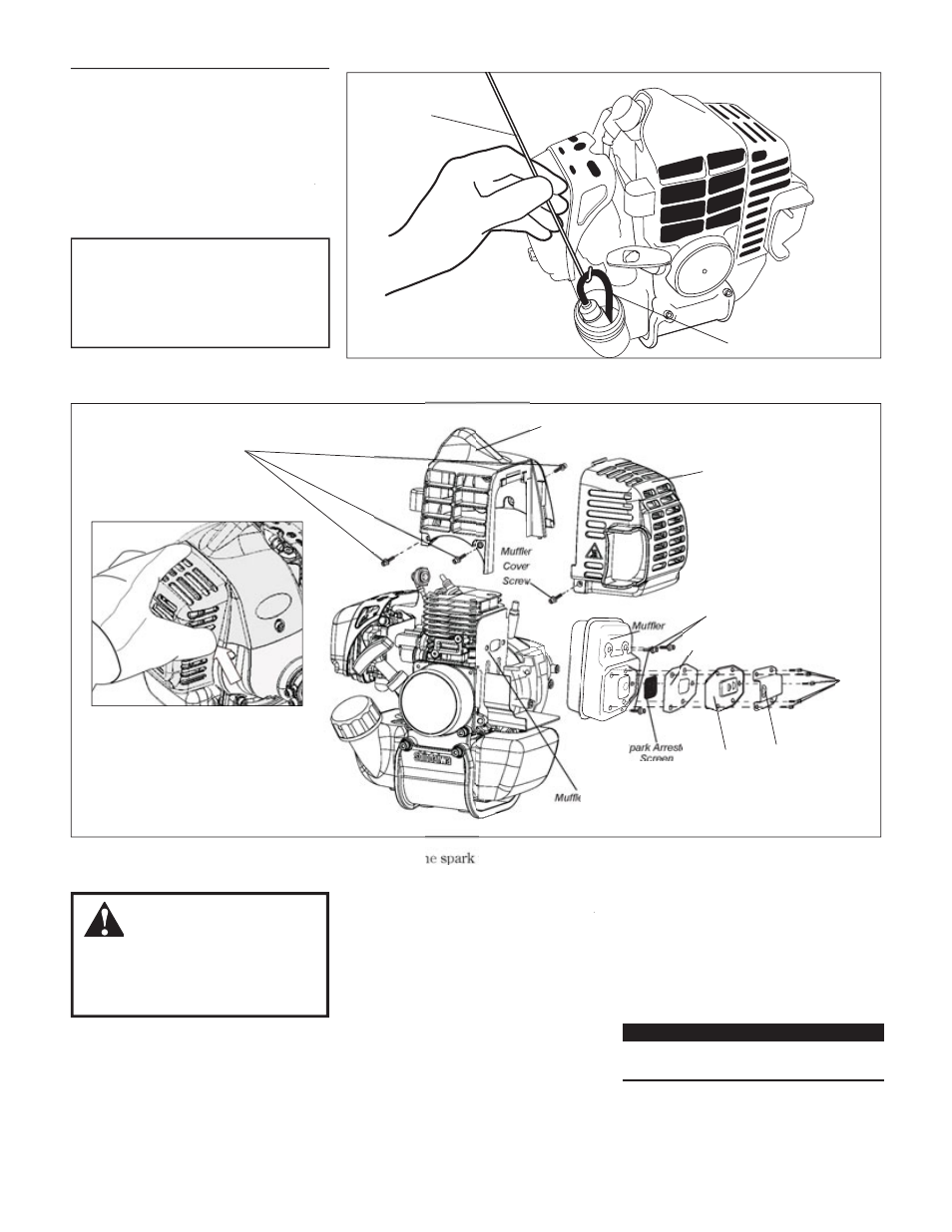
)XHO¿OWHUHOHPHQW
Hooked wire
)XHO¿OWHUPDLQWHQDQFH
Engine Cover
Screws
0XIÀHU&RYHU
Engine Cover
Spark Arrester
Screen
Spark Arrester
Cover
Outlet
Screws
HU*DVNHW
Gasket
0XIÀHU
Screws
16
Maintenance (continued)
Ever y 135 hours of operation, remove
and clean the muffler.
IMPORTANT!
If you note excessive carbon buildup, consult
with an authorized Shindaiwa servicing dealer.
Remove the spark plug boot.
1.
With a 4mm hex wrench remove the
2.
1 muffler cover and 3 engine cover
screws and the engine cover. The muf-
ff
fler cover is attached to the engine
cover at the top and front by tabs. To
remove push inward at arrow area
while pulling outward. See insert
image.
With a Phillips type screwdriver
3.
remove the 5 screws holding the
spark arrester screen and cover to the
muffler.
Remove the screen and clean it with a
4.
stiff bristle brush.
If the engine becomes sluggish and low on
power, check and clean the spark arrester
screen.
WARNING!
Never operate the unit with
DGDPDJHRUPLVVLQJPXIÀHURUVSDUN
arrester! Operating with a missing or
GDPDJHGVSDUNDUUHVWHULVD¿UHKD]DUG
and could also damage your hearing.
Remove and replace the fuel filter element.
Before reinstalling the new filter element,
inspect the condition of all the fuel system
components (fuel pick-up line, fuel return
line, tank vent line, tank vent, fuel cap and fuel
tank). If damage, splitting or deterioration is
noted, the unit should be removed from ser-
rr
vice until it can be inspected or repaired by a
Shindaiwa-trained service technician.
50 hour maintenance
CAUTION!
Make sure you do not pierce the fuel
line with the end of the hooked wire.
The line is delicate and can be dam-
aged easily.
Remove the 3 muffler bolts and the
5.
muffler.
Inspect the cylinder exhaust port for
6.
any carbon buildup.
Gently tap the muffler on a wood sur-
rr
7.
face to dislodge any loose carbon.
Reassemble the spark arrester, muffler
8.
and engine cover in the reverse order
of disassembly.
0XIÁHUPDLQWHQDQFH