I2c serial microprocessor interface, Figure 32. i, Figure 33. i2c example – Silicon Laboratories SI5375 User Manual
Page 90: S i 5 3 x x - r m, Write command read command, C serial microprocessor interface
S i 5 3 x x - R M
90
Rev. 1.2
6.13. I
2
C Serial Microprocessor Interface
When configured in I
2
C control mode (CMODE = L), the control interface to the device is a 2-wire bus for
bidirectional communication. The bus consists of a bidirectional serial data line (SDA) and a serial clock input
(SCL). Both lines must be connected to the positive supply via an external pull-up. In addition, an output interrupt
(INT) is provided with selectable active polarity (determined by INT_POL bit). Fast mode operation is supported for
transfer rates up to 400 kbps as specified in the I
2
C-Bus Specification standard. To provide bus address flexibility,
three pins (A[2:0]) are available to customize the LSBs of the device address. The complete bus address for the
device is as follows:
1 1 0 1 A[2] A[1] A[0] R/W.
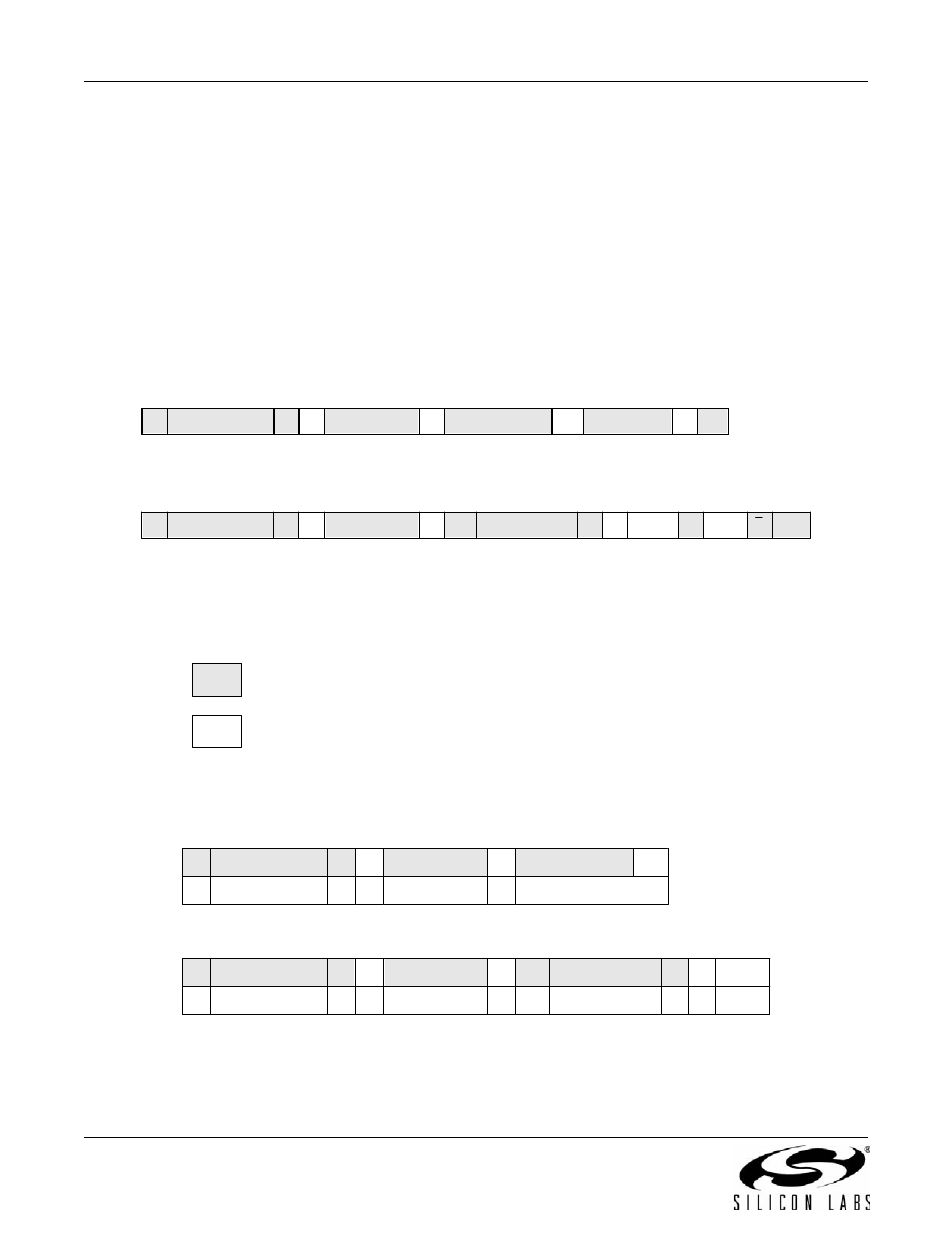
Figure 32 shows the command format for both read and write access. Data is always sent MSB first. The timing
specifications and timing diagram for the I
2
C bus can be found in the I
2
C-Bus Specification standard (fast mode
operation) (See
The maximum I
2
C clock speed is 400 kHz.
Figure 32. I
2
C Command Format
In Figure 33, the value 68 is seven bits. The sequence of the example is: Write register 00 with the value 0xAA;
then, read register 00. Note that 0 = Write = W, and 1 = Read = R.
Figure 33. I
2
C Example
A
Data
A
Data
P
A
1
Slave Address
S
A
Byte
Address
A
0
Slave Address
S
A
Data
A
Data
P
1
Slave Address
S
A
Byte
Address
A
0
Slave Address
S
From master to slave
From slave to master
A – Acknowledge (SDA LOW)
S
– START condition
P – STOP condition
Write Command
Read Command
–address auto incremented after each data read or write
(this can be two separate transactions)
P
A
Data
A
Data
A
Byte
Address
A
0
Slave Address
S
P
A
Data
A
Data
A
Byte
Address
A
0
Slave Address
S
A
Data
1
Slave Address
S
A
Byte Address
A
0
Slave Address
S
Data
0
Write Command
Read Command
A
Data
A
Byte Address
A
0
Slave Address
S
68
W
00
68
R
AA
68
W
00
AA