Regular maintenance, Lubrication, Checking tire pressure – Simplicity 1693763 860M User Manual
Page 17
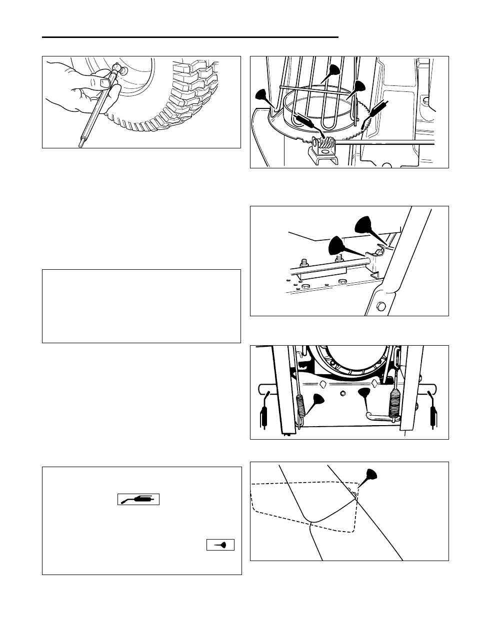
Figure 18. Lubricate Deflector Hinges
04
LUBRICATION NOTES:
1.Grease locations indicated by grease gun symbol:
Use grease fittings when present. Disassemble parts
to apply grease to moving parts when grease fittings
are not installed.
2.Oil locations indicated by oil can symbol:
Do not allow oil to drip onto traction drive or friction
disc.
13
Regular Maintenance
Remove wheels and grease axles once each year.
There are two grease fittings on the auger shaft (Figure
13). Wipe the fittings clean and apply grease, using a
grease gun. Also apply grease on other points indicated.
Apply medium weight (10W) oil to points shown(See
Figures 15 - 18).
Generally, all moving metal parts should be oiled where
contact is made with other parts. Keep oil and grease off
belts, pulley grooves, drive disc, and friction disc.
See lubrication notes at bottom of page.
IMPORTANT NOTE
It is very important that grease fittings on the auger shaft
are lubricated regularly. If auger rusts to shaft, damage to
worm gear may occur if shear pins do not break.
To prevent wheels rusting to axles, it is also necessary
to remove the wheels and grease the axles regularly.
LUBRICATION
Figure 15. Lubricate Points Where Chute Contacts
Flange (oil); Lubricate Ring Gear and Pinion Gear
While Rotating Spout (grease)
Figure 16. Lubricate Point Where Control Rods Pass
Through Bracket.
Figure 17. Grease Axles & Lubricate Control Levers
CHECKING TIRE PRESSURE
The air pressure in each tire should be 20 psi (136 kPa)
and should be equal for both tires for best performance.
Be sure to keep caps on valves to prevent entry of debris
into the valve stem when tires are filled.
Figure 14. Checking Tire Pressure