System Sensor 2151 User Manual
Page 3
D100-04-00
3
I56-581-07R
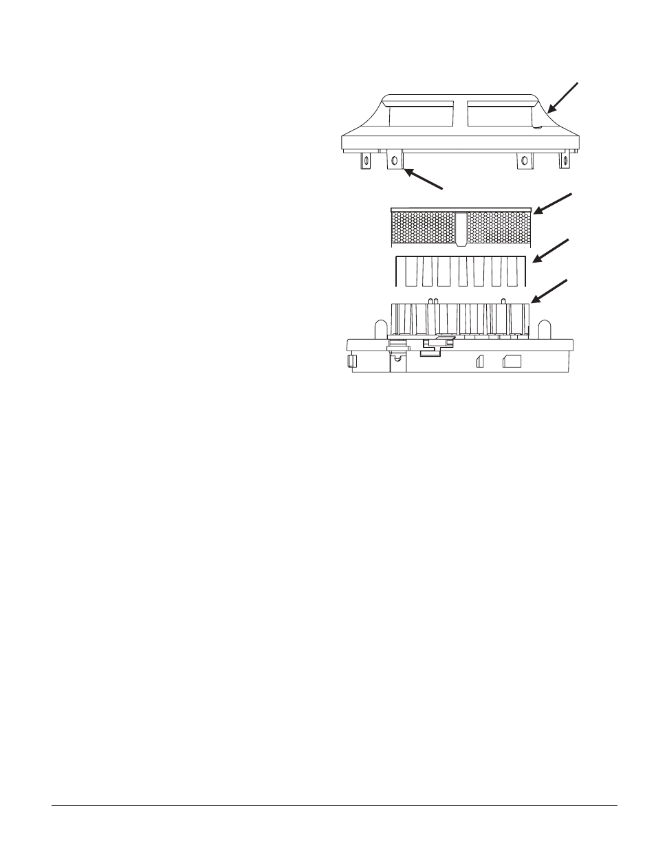
SENSING
CHAMBER
SENSING
CHAMBER
COVER
SENSOR
SCREEN
COVER REMOVAL
TABS
SENSOR
COVER
Figure 2:
C0253-00
1. Remove the detector cover by prying away the four
side tabs with a small-bladed screwdriver, and then
pulling the cover from the base.
2. Vacuum the screen carefully without removing it. If
further cleaning is required continue with Step 3, oth-
erwise skip to Step 8.
3. Remove the screen assembly by pulling it straight out
(see Figure 2).
4. Remove the sensing chamber cover by pulling it
straight out.
5. Clean the vaned chamber piece by vacuuming or
blowing out dust and particles.
6. Replace the sensing chamber cover, aligning the arrow
on the top with arrow on the printed circuit board.
7. To replace the screen, place it over the chamber
assembly, turning it until it snaps into place.
8. Replace the cover using the test module socket and
LEDs to align the cover and then gently pushing it
until it locks into place.
9. Reinstall the detector.
10. Test the detector as described in TESTING.
11. Reconnect disabled circuits.
12. Notify the proper authorities that the system is back
on line.
Special Note Regarding Smoke Detector Guards
Smoke detectors are not to be used with detector guards
unless the combination has been evaluated and found
suitable for that purpose.