Table 6-1 card information structure – SanDisk CompactFlash Extreme III User Manual
Page 94
CIS Description
SanDisk CompactFlash Card OEM Product Manual
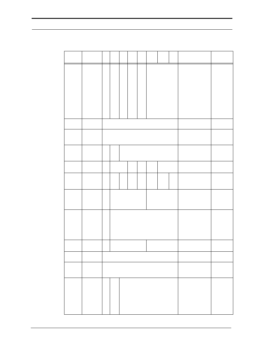
Table 6-1
Card Information Structure
Attribute
Offset
Data
7
6
5
4
3
2
1
0
Content Description
CIS
Function
0D6h
21h
X
0
R
0
P
1
RO
0
A
0
T
1
Power-Down
and Twin Card.
TPCE_MI
T: Twin Cards Allowed
A: Audio Supported
RO: Read Only Mode
P: Power Down
Supported
R: Reserved
X: More Misc Fields
Bytes
0D8h
1Bh
CISTPL_CE
Configuration
Entry Tuple
Tuple Code
0DAh
06h
Link to Next Tuple is 6
Link to
Bytes. Also limits size of
Next Tuple
this tuple to 8 bytes.
0DCh
01h
I
0
D
0
Configuration Index
1
I/O Mapped Contiguous
16
3.3V Configuration
TPCE_INDX
0DEh
01h
M
MS
IR
IO
T
P
P: Power Info type
TPCE_FS
0
0
0
0
0
1
0E0h
21h
R
0
DI
0
PI
1
AI
0
SI
0
HV
0
LV
0
NV
1
PI: Peak Current
NV: Nominal Operation
Supply Voltage
Power
Parameters
for V
CC
0E2h
B5h
X
Mantissa
Exponent
Nominal Operation
Nominal
1
6h = 3.0
5h = 1
Supply Voltage = 3.0V
Operation
Supply
Voltage
0E4h
1Eh
X
1Eh
+.30
Nominal
0
Operation
Supply
Voltage
Extension
Byte
0E6h
4Dh
X
0
Mantissa
9h = 4.5
Exponent
5h = 10
Max. Average Current
over 10 ms is 45 mA
Max. Average
Current
0E8h
1Bh
CISTPL_CE
Configuration
Entry Tuple
Tuple Code
0EAh
12h
Link to Next Tuple is 18
Link to
Bytes. Also limits size of
Next Tuple
this tuple to 20 bytes
0ECh
C2h
I
1
D
1
Configuration Index
2
AT Fixed Disk Primary
I/O Address
Configuration
TPCE_INDX
Configuration Index for
this entry is 2. Interface
Byte follows this byte.
Default Configuration
02/07, Rev. 12.0
6-10
© 2007 SanDisk Corporation