Installation step 3, Wiring, Wiring diagram – Soundstream Technologies SA.244 User Manual
Page 8
INSTALLATION STEP 3
WIRING
POWER AND GROUND
To assure maximum output from your amplifier, use high quality, low-loss power
and ground cables. Soundstream SA amplifiers incorporate gold-plated barrier
strips for maximum power transfer and protection from corrosion. The screw
terminals back out
for use with spade & ring terminals, as well as bare
wire.
Determine from the chart below the minimum gauge power and ground wire for
your application.
up
up to 20’
Soundstream Power80
Soundstream Power80
or
00
or 8 or 10 ga.)
Soundstream Power80
Soundstream Power80
CIRCUIT BREAKERS/FUSES
EXTERNAL
Like all other amplifiers, the Soundstream
must be fused near the
battery. A fuse or circuit breaker must be located within 18” of the battery. This
will prevent a fire in the event of a shorted cable. See the chart below to
determine the
value of your battery fuse/circuit breaker.
Model
Amplifier Fuse
Battery Fuse/
Circuit Breaker
25 amp automotive
30 amp
30 amp automotive
30 amp automotive
40 amp
40 amp
(Continued
on page 15)
{Continued
from page 14)
INTERNAL
The Soundstream amplifiers are fused internally with automotive-type fuses.
The fuses are accessible
via a plastic plug
on the bottom of the amplifier. Never
replace the fuses with a higher value than what is supplied. This may
result amplifier damage and
void
warranty!
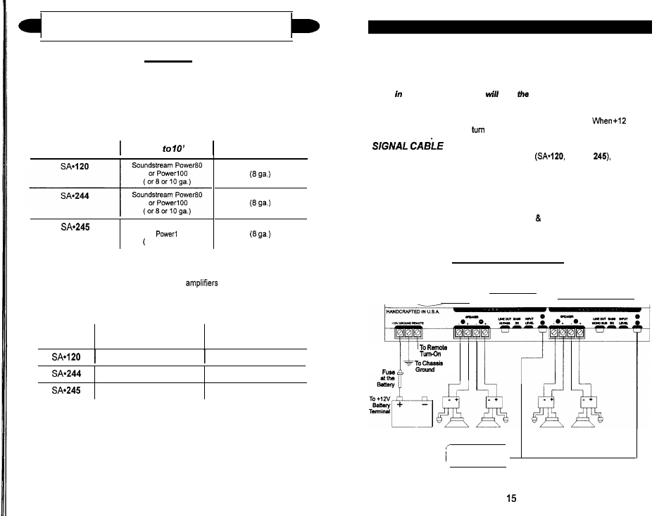
REMOTE TURN-ON
Connect the ‘Remote” to the turn-on lead from the source unit.
volts
is received, the amplifier will
on.
Depending on your application and amplifier
244, or
you may
use one, two, or three pairs of signal cables to drive your amplifier. To
guarantee optimum performance, use a high-quality cable that will be easy to
install and has minimal signal loss.
SPEAKER CABLE
Use a high quality, flexible, multi-strand cable for best performance and
longevity. Soundstream Speaker120 & 160 (12 16 gauge) are ideal.
WIRING DIAGRAM
HEAD UNIT
14