Spirit XE 200 User Manual
Page 12
XE100 / XE200 / XE300 Elliptical
11
2. Install the connecting arm covers (57,57-1 & 58,58-1) over the connection of the rod end and
handle bars (10 & 11) with eight M5 x 15m/m Phillips Head Screws (105) and eight 3.5x12m/m
self tapping screws (87) by using the Phillips head screw driver.
3. Install the two Wheel Covers (52) using the four M5x15m/m Phillips Head Screws (105).
4. Locate the two Rear Stabilizer Covers (19,20) and two Middle Stabilizer Covers (19,20) for the
Rear Rail Assembly and install with four M5 x 15m/m Screws (105). Then install front stabilizer
cover (49) with two M5 x 15m/m Screws (105).
5. Install the Front Handle Bar Covers (54-1 left, 55-1 right) and Rear Handle Bar Cover (54 left,
55 right) over the Handle Bar axle connections with the six 3.5x10m/m Self Tapping Screws
(87).
6. Install the front (122) and rear (121) console mast covers with three M5 x 15m/m Screws (105)
and two 3.5x12m/m Self Tapping Screws (87).
PLEASE ENSURE ALL FASTENERS ARE TIGHT AFTER THE COMPONENTS HAVE BEEN
ASSEMBLED.
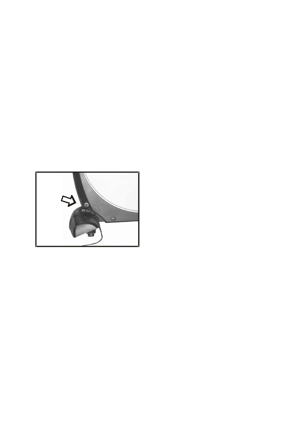
POWER CONNECTOR LOCATED ON
FRONT, LEFT HAND SIDE OF UNIT.