Assembly – Shindaiwa AH254 User Manual
Page 7
7
Assembly
Before assembling, make sure you
have all the components required for a
complete unit:
Unit assembly
■
Prior To Assembly
Kit with this manual and tool kit for
■
routine maintenance.
Cutter blade cover
■
Carefully inspect all components for
damage.
IMPORTAnT!
The terms “left”, “left-hand”, and
“LH”; “right”, “right-hand”, and “RH”;
“front” and “rear” refer to directions as
viewed by the operator during normal
operation.
The cutter assembly can be adjusted
to eleven different positions ranging
from 120° to 270° from the outer tube
as shown. Always make sure the lock
latch is securely locked after each
adjustment.
Cutter Assembly Positions
Position the hedge trimmer on a
1.
flat, level surface.
With your right hand, grasp the
2.
outer tube near the handle. With
your left hand, grip the adjustment
lever on the cutter assembly. With
the index finger of your left hand,
press the latch lock. With your left
thumb, press the latch release.
270°
120°
Various blade
positions
possible
Cutter
Assembly
Positions
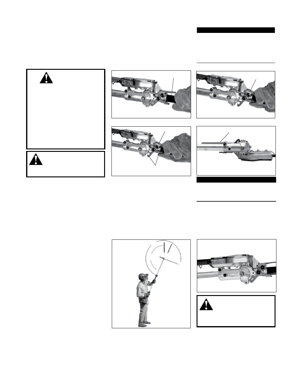
Adjusting the Hedge Trimmer Cutter Assembly
The cutter blades are very sharp.
■
Do not grasp the blades with
your hands. Always use gloves
when working near the cutter
assembly.
Do not allow the blades to con-
■
tact your body.
Do not touch the cutter blades
■
when the engine is running. The
blades can oscillate even if the
engine is idling.
IMPORTAnT!
The latch lock provides an interlock to
help prevent inadvertent depression of
the latch release.
wARnInG!
Latch Release
Grasp the outer tube near the handle
Adjustment Lever
Adjustment Lever
Pivot the cutter assembly using the
adjustment lever...
Press the latch lock
Make sure the latch lock and the latch release
return securely to the straight ahead position
With the engine off, install the
1.
blade cover onto the blade.
Using the procedures described
2.
above, rotate the cutter assembly
so it is parallel to the tube. Make
sure the latch lock and the latch
release return securely to a locking
position.
Make sure the blade cover is in
3.
place on the cutters before storing or
transporting.
Gearcase rotated to the storage/
transportation position
Adjusting for Storage or Transportation
wARnInG!
Never run the engine when
adjusting the cutter assembly.
Adjusting for Storage or Transportation
Latch Lock
While holding the latch release
3.
down, pivot the cutter assembly
away from you using the adjust-
ment lever until it is at the desired
cutting angle.
Release the latch lock and the
4.
latch release. Make sure the latch
lock and the latch release return
securely to the locked position.
Remove the cover from the cut-
5.
ter blade. The engine now may be
started (refer to the section ”Starting
the Engine”).
wARnInG!
Never run the engine when
adjusting the cutter assembly.
Latch Lock