1 control panels, Qa alarm indicator and key inhi indicator, Qs player button and recorder button – Sony MSW-M2000 User Manual
Page 22
Chapter 2
Location and Function of Parts
2-12
Chapter 2
Location and Function of Parts
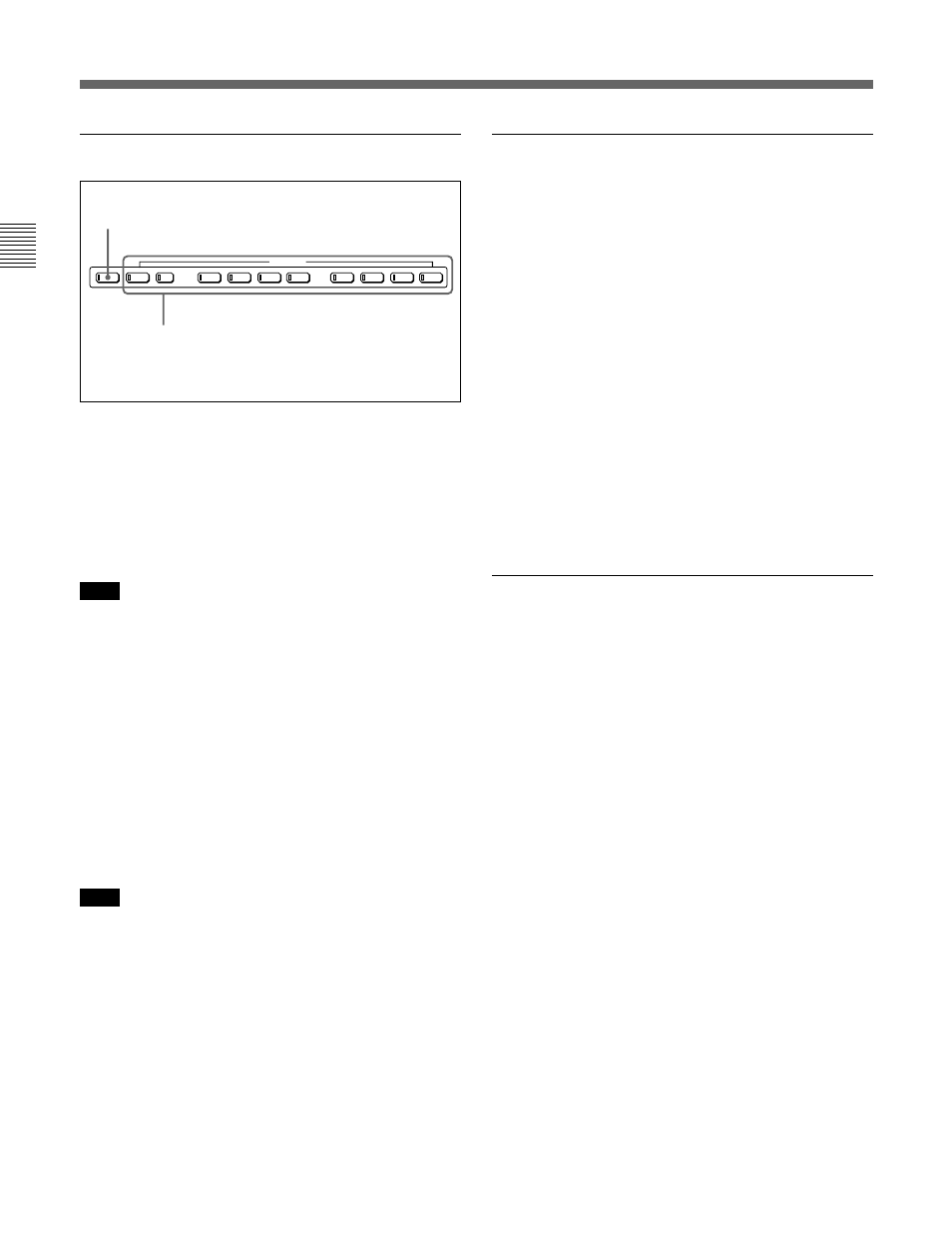
q; Editing mode setting section
1
ASSEMBLE button
Press this button, turning it on, to carry out assemble
editing
1)
.
All signals (video signals, audio signals, time code
signals, and so on) are recorded together.
Press the button again, turning it off, to exit from
assemble editing mode.
Note
When even one of the INSERT buttons is lit, the
ASSEMBLE button does not work. To use the
ASSEMBLE button, turn off all the lit INSERT
buttons.
2
INSERT buttons
Press the corresponding button, turning it on, to select
a signal for insert editing
2)
. Press the button again,
turning it off, to cancel the selection.
VIDEO button: Selects the video signal.
TC (time code) button: Selects time code.
CH1 to CH8 (audio channels 1 to 8) buttons:
Select the signals on audio channels 1 to 8.
Note
When the ASSEMBLE button is lit, none of the
INSERT buttons work. To use INSERT buttons, press
the ASSEMBLE button, turning it off.
qa ALARM indicator and KEY INHI
indicator
ALARM indicator
This lights when a hardware error is detected on the
unit, and goes off when the error is resolved.
When this indicator is lit, an error message appears in
the time data/menu display section. If you are using
the SDI OUTPUT 3 (SUPER) or COMPOSITE
VIDEO OUTPUT 3 (SUPER) connector, then when
the setting of F4 (CHARA) in function menu page 4 is
ON, the error message also appears on the monitor
screen.
For details on error messages, refer to Section 1-24 in the
Maintenance Manual Volume 1.
KEY INHI (inhibit) indicator
This indicator lights when the KEY INHIBIT switch
on the switch panel (see page 2-15) is set to ON.
qs PLAYER button and RECORDER
button
When you carry out editing using a VTR connected to
the REMOTE 1-IN(9P) or REMOTE 1-OUT(9P)
connector (see page 2-19) as the player and this unit as
the recorder, these buttons select which VTR the
editing control buttons and tape transport buttons on
this unit control.
PLAYER: The editing control buttons and tape
transport buttons on this unit control the external
player VTR.
RECORDER: The editing control buttons and tape
transport buttons on this unit control the recorder,
that is to say, this unit.
When this unit is being used in standalone mode,
neither button functions.
VIDEO
TC
CH1
CH5
CH6
CH7
CH8
CH2
CH3
CH4
INSERT
ASSEMBLE
2
INSERT buttons
1
ASSEMBLE button
1) Assemble editing: Editing in which new video/audio is
added in sequence to the end of existing recorded video/
audio.
..........................................................................................................................................................................................................
2) Insert editing: Editing in which new video/audio is added
to an intermediate position of existing recorded video/
audio.
2-1 Control Panels