Time events 1 to 5 – Sonic Alert Digital Program Controller DCP301 User Manual
Page 57
Chapter 5. FUNCTIONS
5-6
■
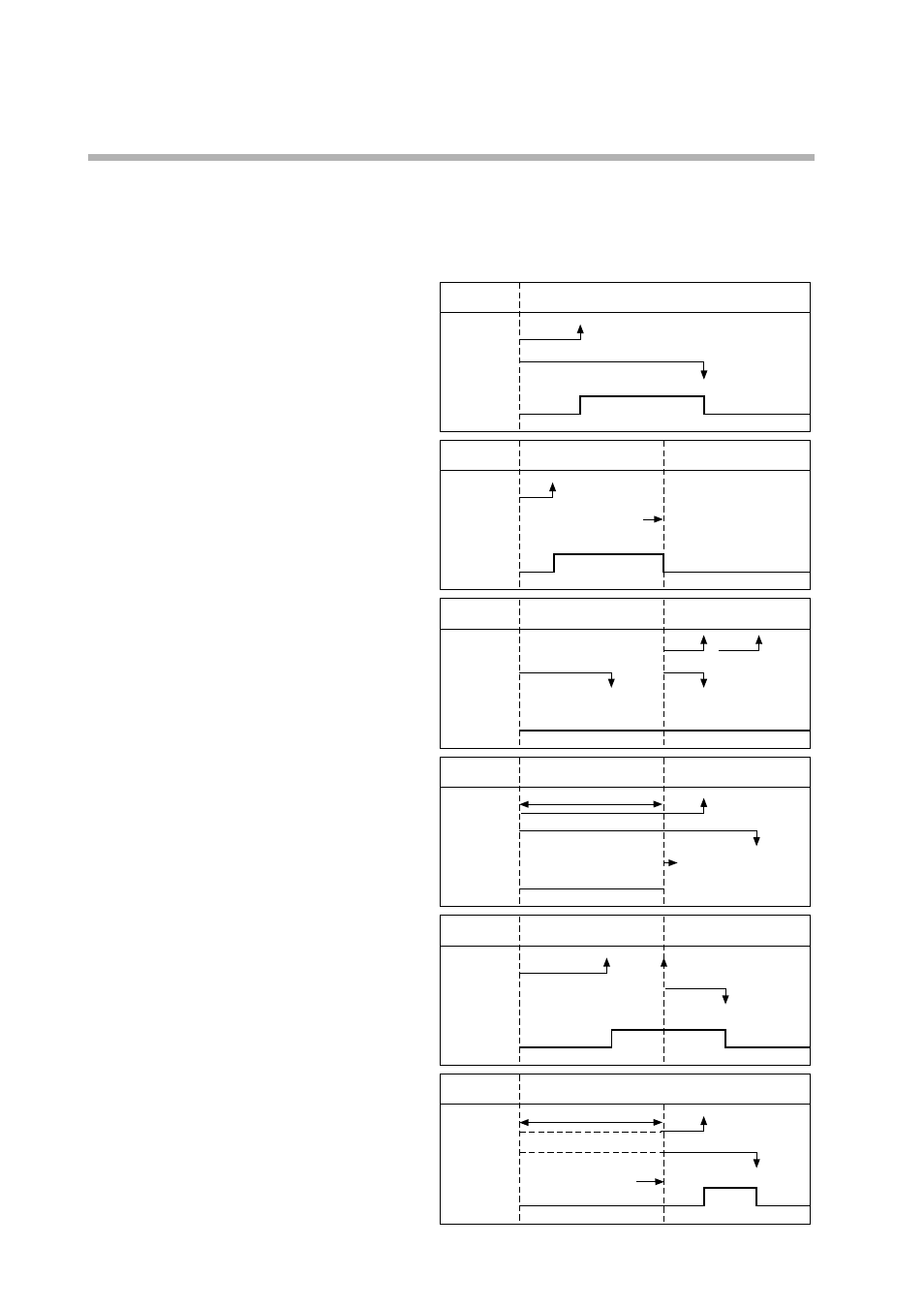
Time events 1 to 5
Either of time events or segment No. events can be selected by the time event type item
in the event configuration data setup.
● Time events
Segment
1
ON time
OFF time
Output ON
Output OFF
ON Segment 2 3 ON time OFF time Output ON Output OFF Output turns OFF at Segment 5 6 ON time OFF time Output ON Output OFF ON Segment 3B 3C ON time OFF time Output ON Output OFF No ON ON=OFF ON>OFF Segment 4 Segment time 5 ON time OFF time Output ON Output OFF G.Soak standby ON-OFF time is invalid Advance to ON=0 Segment 7 ON time OFF time Output ON Output OFF Segment time start The ON and OFF times or only the ON time can • When the ON time is smaller than the OFF time, output is ON for the duration from the • When only the ON time is set, output is ON for the during from the ON time to the seg- • When both the ON time and OFF time are not set, output is OFF. • Setting only the OFF time without an ON time is not possible. • Setting an ON time to be greater to or equal than the OFF time is not possible. • Only ON and OFF times set within the seg- ment time are valid. Times straddling the next Accordingly, the ON and OFF times settings However, ON and OFF times set for segment • When the ON time is set to 0 (no OFF time setting, or OFF time is greater than 0), output If output at the previous segment end point was • The G.Soak standby time is not included in the ON and OFF times.
end of segment even if
OFF time is not set.
continued
even if set in excess of
segment 4 time.
segment 5
be set for each event No. and segment. The fol-
lowing describes ON/OFF of output.
ON time to the OFF time.
(See segments 1, 6 and 7 in the figure.)
ment end point.
(See segments 2 and 5 in the figure.)
(See segment 3 in the figure.)
(See segment 3B in the figure.)
(See segment 3C in the figure.)
segment are invalid. The ON and OFF times
set in the next segment are valid.
(See segments 4 and 5 in the figure.)
at the segment end point are ignored.
end points when the END mode is shifted to
are valid.
(See segment 9 in the figure, and compare with
segment 10 in the END mode.)
becomes OFF at time 0.
ON at this time, the output status at the seg-
ment switching point does not momentarily
become OFF.
(See segments 5 and 6 in the figure.)
(See segment 7 in the figure.)