Vcr, dvd recorder, Camcorder/ video game, Audio signals video signals – Sony 3-289-450-45(1) User Manual
Page 27: On the front panel)
27
GB
Ge
tting Star
te
d
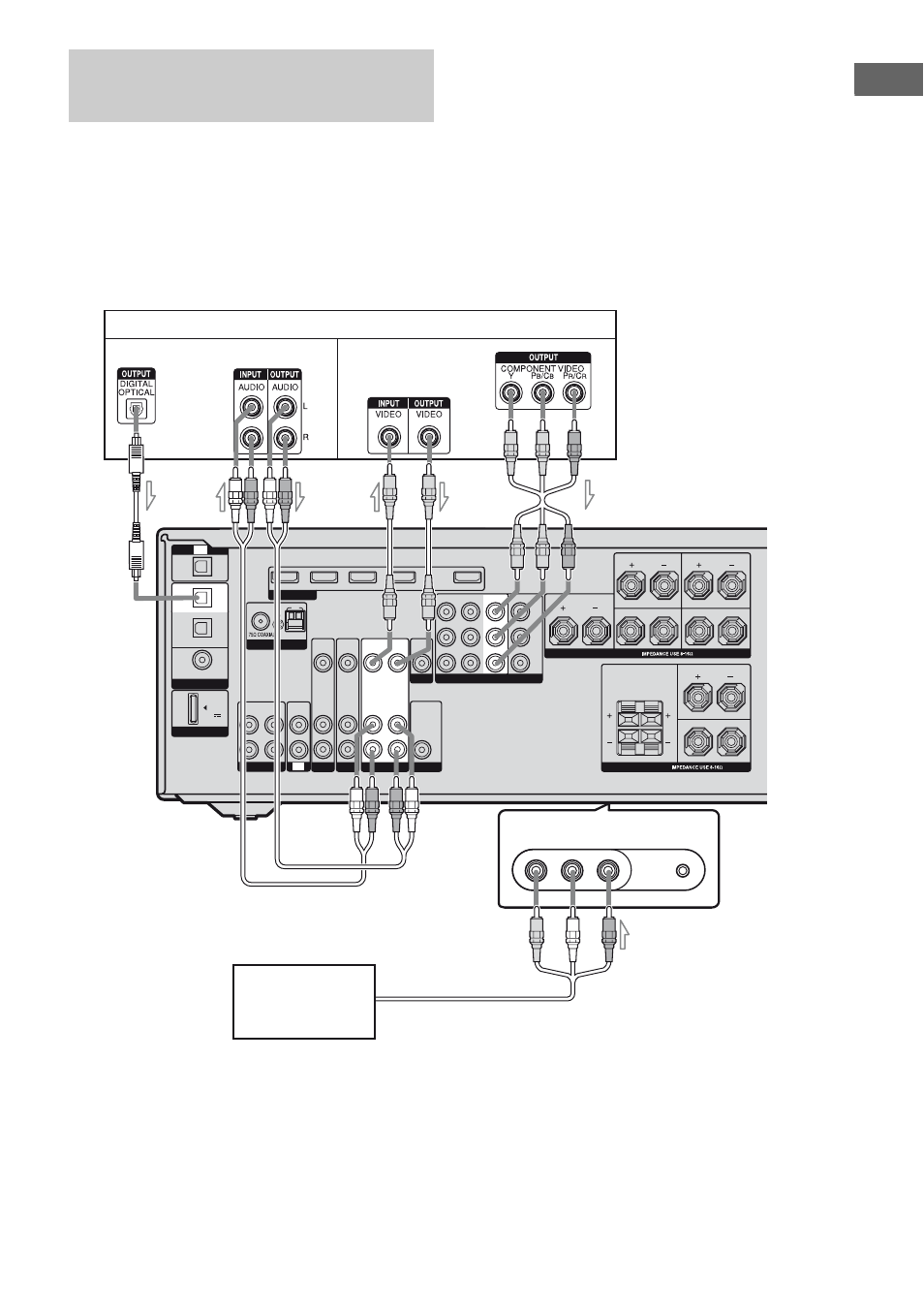
The following illustration shows how to
connect a component which has analog jacks
such as a VCR, DVD recorder, etc.
It is not necessary to connect all the cords.
Connect audio and video cords according to
the jacks of your components.
Notes
• Be sure to change the factory setting of the VIDEO
1 input button on the remote so that you can use the
button to control your DVD recorder. For details,
see “Programming the remote” (page 83).
• You can also rename the VIDEO 1 input so that it
can be displayed on the receiver’s display. For
details, see “Naming inputs” (page 80).
• When connecting optical digital cords, insert the
plugs straight in until they click into place.
• Do not bend or tie optical digital cords.
Connecting components with
analog video and audio jack
VIDEO 2 IN/PORTABLE AV IN
AUTO CAL MIC
L
R
DIGITAL
DMPORT
(ASSIGNABLE)
OPTICAL
OPTICAL
IN
COAXIAL
DVD
IN
TV
SAT
IN
DC5V
0.7A MAX
AM
FM
ANTENNA
SAT IN
DVD IN
BD IN
VIDEO 1 IN
OUT
HDMI
AUDIO
OUT
SPEAKERS
SPEAKERS
CENTER
SURROUND BACK
FRONT A
FRONT B
L
R
SURROUND
L
R
L
L
R
R
COMPONENT VIDEO
SAT IN
DVD IN
Y
P
B
/
C
B
P
R
/
C
R
AUDIO
IN
VIDEO
IN
SAT
AUDIO
IN
VIDEO
IN
MONITOR
IN
TV
OUT
AUDIO
OUT
VIDEO
OUT
AUDIO
IN
VIDEO
IN
VIDEO 1 IN
SA-CD/CD/CD-R
VIDEO
L AUDIO R
VIDEO 1
IN
IN
VIDEO 1
VIDEO
OUT
MONITOR OUT
SUBWOOFER
DVD
VCR, DVD recorder
B
Camcorder/
video game
E
Audio signals
Video signals
C
A
Optical digital cord (not supplied)
B
Audio cord (not supplied)
C
Video cord (not supplied)
D
Component video cord (not supplied)
E
Audio/video cord (not supplied)
A
D
(On the front panel)