Rear panel fea tures, Chapter 1 5. triggers and relay, Speaker-level outputs – Sunfire Radio User Manual
Page 12: Audio/video inputs, Audio/video outputs, Component video in, Component video out, User's manual
User's Manual
12
AM
GND
FM
75
Ω
RIGHT
SURROUND
RIGHT
MAIN
CENTER
LEFT
MAIN
LEFT
SURROUND
SURROUND
BACK
RIGHT
LEFT
OPTIONAL:
SIDE-AXIS
OR
ZONE2
DVD
SAT
VID1
VID2
VCR
CD
PHONO
DAT
R
L
R
L
R
L
C
r
Y
b
R
L
COMP
VIDEO
S
VIDEO
TAPE
DAT
TAPE
LEFT
L SUR
CEN
LB SUR
FIXED MAIN ZONE2
PHONO
DAT
TAPE
DAT
TAPE
FIXED MAIN ZONE2
LEFT
DVD
DVD
CD
SAT
DAT
VID1
VID2
SAT
VID1
CD
LEFT SUR
CENTER
SUB2
LB SUR
L SIDE AXIS
RIGHT
RIGHT SUR
SUB1
SUB3
RB SUR
R SIDE AXIS
RIGHT
R SUR
SUB
RB SUR
MAIN
VCR
VID2/MON2
DVD
SAT
VID1
VID2
VCR
CD
MAIN
VCR
VID2/MON2
DVD
SAT
VID1
VID2
VCR
CD
MAIN
VCR
VID2/MON2
DVD
SAT
VID1
MAIN
MAIN
ZONE2
REPLACE WITH ORIGINAL
FUSE TYPE AND RATING
ZONE2
12VDC
12VDC
12VDC
MAIN ZONE
MON2
TRIGGERS
I R
COMPONENT
OUT
AUDIO/VIDEO OUTPUTS
AUDIO/VIDEO INPUTS
COMPONENT VIDEO IN
RS-232
AUDIO INPUTS
AUDIO OUTPUTS
8-CHANNEL INPUTS
STEREO OUTPUTS
LINE LEVEL AUDIO OUTPUTS
SPEAKER LEVEL AUDIO OUTPUTS
DIGITAL AUDIO INPUTS
SIDES
DIGITAL OUT
IEEE
1394
AC INPUT
AC FUSE
Sunfire
Ultimate Receiver II
120 VAC 60 Hz
C
R
L
MANUFACTURED UNDER LICENSE
FROM DIGITAL THEATER SYSTEMS,
INC. US PAT. NO. 5,451,942,
5,956,674, 5,974,380, 5,978,762 AND
OTHER WORLD-WIDE PATENTS
ISSUED AND PENDING. "DTS",
"DTS-ES EXTENDED SURROUND"
AND "NEO:6" ARE TRADEMARKS
OF DIGITAL THEATER SYSTEMS,
INC. COPYRIGHT 1996, 2000,
DIGITAL THEATER SYSTEMS, INC.
ALL RIGHTS RESERVED.
MANUFACTURED UNDER LICENSE
FROM DOLBY LABORATORIES.
"DOLBY", "PRO-LOGIC" AND THE
DOUBLE-D SYMBOL ARE
TRADEMARKS OF DOLBY
LABORATORIES.
Made in Snohomish, Washington, U.S.A.
CHAPTER 1
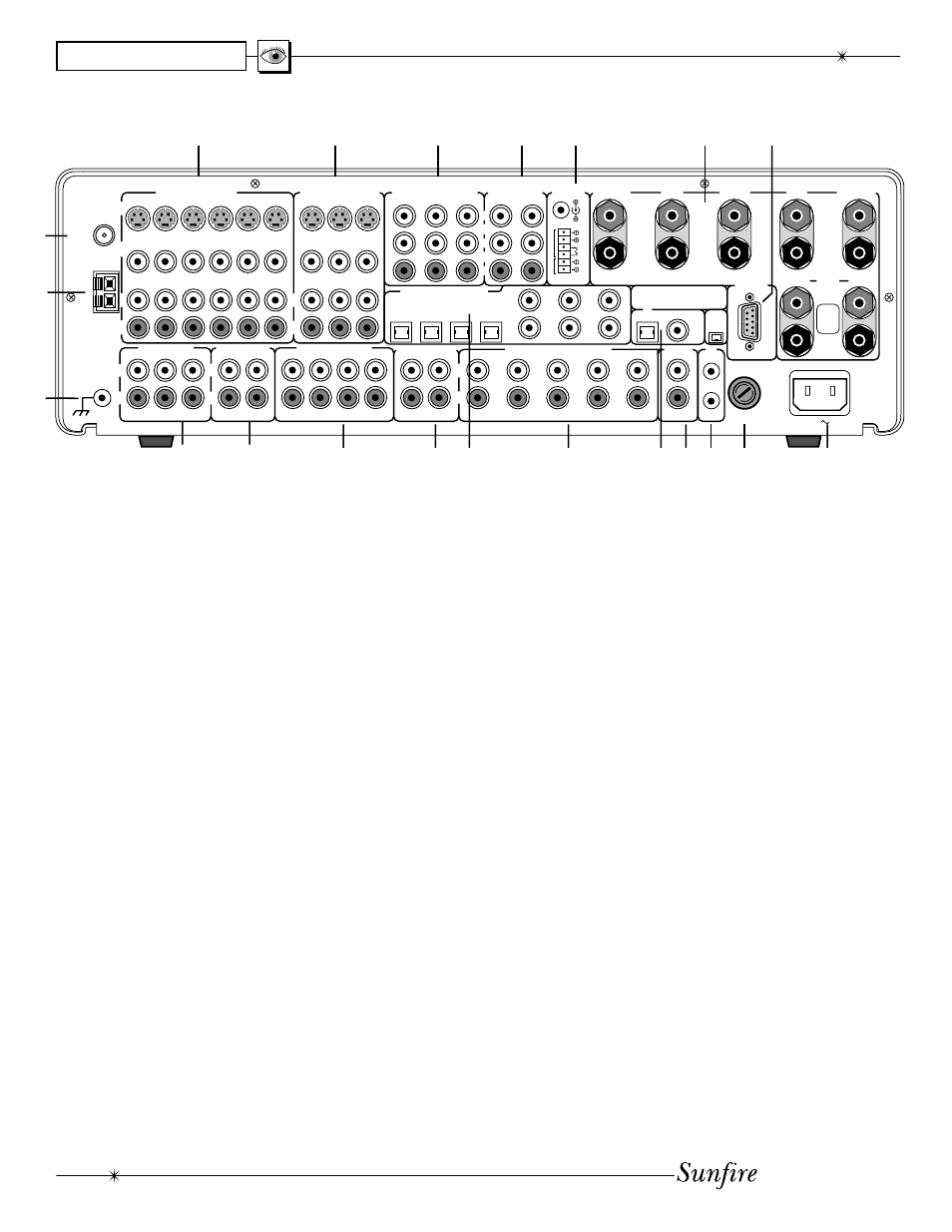
5. Triggers and Relay
The relay switch is normally open,
and it will close after a short delay,
when selecting a source. This can
be used in in stal la tions to trigger
video screen deployment, or other
custom purposes. The OSD
INPUTS menu lets you choose
which inputs activate the relay.
The +12 VDC outputs are on
whenever their zone is enabled.
They can be used to automatically
turn on ampliÞ ers for example.
The 1/8” mini-jack is wired in
parallel with the terminals. Do not
exceed a current draw of 500mA
total for both outputs.
6. Speaker-level Outputs
These speaker-level audio out-
puts connect to the inputs of your
speakers. The outputs are: front
left, front right, center, left sur-
round, and right surround. The
two lower (Aux) outputs can be
assigned as surround back out-
puts, Zone 2 outputs or side-axis
outputs, see page 41 for details.
Rear Panel Fea tures
1. Audio/Video Inputs
These audio, composite-video
and S-video inputs con nect to the
outputs of your audio video com-
po nents. When these inputs are
selected, the audio will be heard
in your system and the video will
be seen on the TV screen. VID2
can be used for a second VCR.
2. Audio/Video Outputs
MAIN: connects to the inputs of a
TV monitor, where the video
of any selected input and the
On Screen Display (OSD) can
be viewed. The audio con nec -
tions allow you to listen to any
selected audio source through
your TV’s speak ers.
VCR: connects to the inputs of a
VCR to allow recording.
VID2/MON2: connects to the input
of a second VCR for recording,
or to a second TV. When con-
Þ gured in the OSD for “VID2,”
this output is muted whenever
the VID2 input is selected. This
prevents feedback; also there
is no OSD then on this output.
When conÞ gured for “MON2,”
the output is always active, the
same as the Main output.
Note: Analog audio signals are
present at these L and R outputs
even if a digital input has been
selected. The output is a 2 chan-
nel downmix if the digital source is
more than 2 channels.
3. Component Video In
These inputs con nect to the
component video outputs of your
DVD, SAT or other video source
(VID1) if they have this advanced
capability. When these inputs are
se lect ed, the Receiver's Pro-
ces sor will au to mat i cal ly route
any video signals going into these
jacks to the component video
outputs. Note that component
video provides the best picture
compared to composite or
S-video. The Receiver can also
switch HDTV signals.
4. Component Video Out
If your TV Monitor has component
video inputs, connect them to
these outputs. If you select DVD,
SAT or VID1, then any video sig-
nals going to the component
inputs, will pass through to your
TV monitor.
1
2
3
4
6
5
7
8
9
10
11
12
13
14 15
17 18
21
16
19 20