Reinstallation of circuit board, Installation cabinet mounting 14 – System Sensor PDRP-1001 User Manual
Page 14
2. Installation
Cabinet Mounting
14
PDRP-1001 Instruction Manual PN 50734:D0 04/06/01
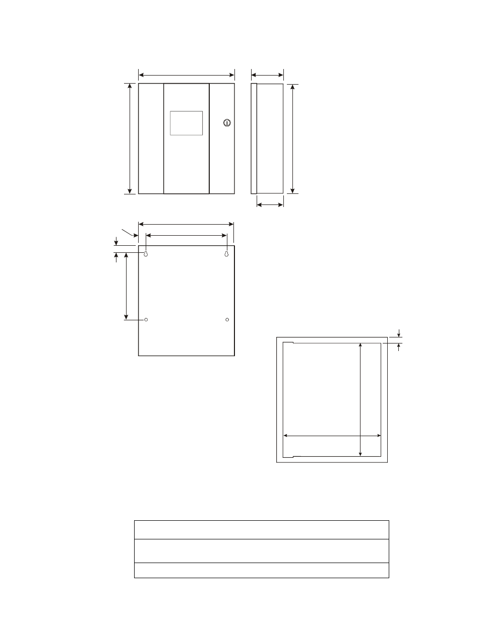
The figure below shows the exterior dimensions and mounting hole locations for the cabinet backbox and
dimensions of the optional trim ring:
Figure 2 Cabinet Mounting Dimensions
Reinstallation of Circuit Board
Reinstall the printed circuit board as follows:
Step
Action
1
Position circuit board over stand-offs on backbox rail and secure with four
(4) phillips screws. Tighten securely.
2
Connect transformer wires to J1 connector on circuit board.
14.625”
(37.15cm)
16.125”
(40.96cm)
5.375”
(13.65cm)
16.00”
(40.64cm)
4.75”
(12.07cm)
14.50”
(36.83cm)
12.50”
(31.75cm)
9.50”
(24.13cm)
1.00”
(2.54cm)
1.00”
(2.54cm)
1.5”
(3.81cm)
16.125”
(40.96cm)
14.625”
(37.15cm)
M
S
44
-c
abd
im
.c
dr
MS
4
4-t
ri
mrin
g
.cd
r