Sierra Products EasyFire MODEL EFI 4000 User Manual
Page 18
18
Com ponent Adjustm ents and Replacem ent:
Main Control Board - Main control board is located in the lower right pedestal (3801/5001) or lower right rear - 4001 insert
and right switch plate for the 5001U. The control board is held in place with several phillips screws.
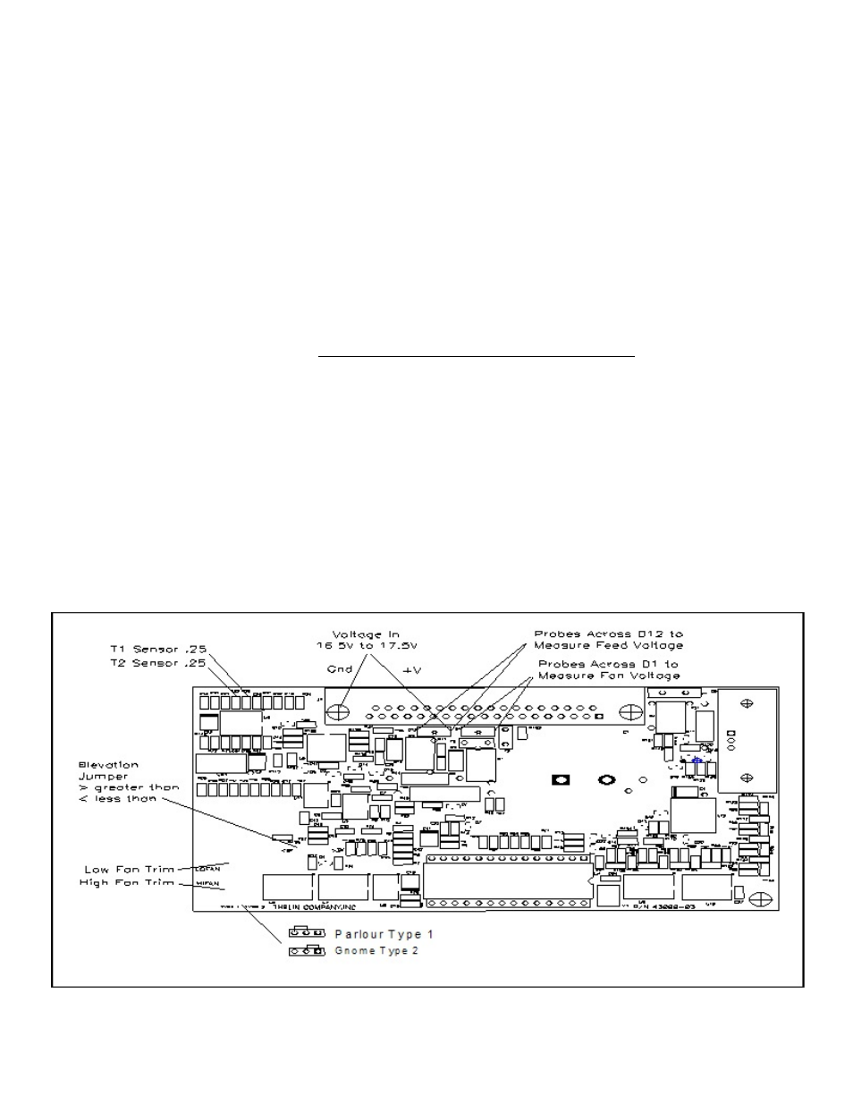
Fan speed adjustm ents are accom plished by turning the LOW and HIGH fan pots on the lower right corner. These
adjustm ents are m ade in the corresponding run m ode. Factory settings are based on fan voltage as read across the m otor
term inals 6.8VDC LOW , and 9.0VDC HIGH.
A GREEN LED light flashes on the control board to confirm AC or DC power is present.
Switch Board - Switch board is attached to access panel with several phillips screws. Harness plugs into bottom of switch.
Sensors - Access for sensors is through the rear panels. Both the T-1 and T-2 sensors are the sam e sensor type m ounted
differently. T-1 is m ounted on the exhaust side of the com bustion fan housing. It is held in place with a tie wrap. T-1 sensor
allows for cabinet air to drawn through the high tem p plastic holder. W hen door is open or flue blocks the flow reverses. T-
2 sensor is attach to a alum inum block and attached to the m anifold. W ire harness connections should be secure and not
pulled tight.
Additional inform ation is available on line@
Technical Custom er Service - 909-399-3355x29
Red Light Fault Indications:
W hen the Hi-Tem p/Flue indicator light com es on (red lite beneath control knob) it m eans a fault has been detected in
either the flue system , over tem perature, or fan/feed m otor.
Slow Flash Red Light - Indicates a blocked flue. Check flue and clean out for built up ash deposits.
Solid Red Light - Indicates an over tem perature. Check the air intake at rear of unit. Turn the feed trim down 25% to
reduce fuel rate.
Fast Flash Red Light - Requires unit to be unplugged to reset. Indicates a feed m otor jam or fan m otor fault. Fan m otor
test would require running unit on “fan and clean” only to determ ine if red light indication is repeated. If not, feed system is
jam m ed and requires the hopper access cover to be rem oved and jam m ed m aterial to be rem oved