Assembly (continued) – Shindaiwa 89303 User Manual
Page 9
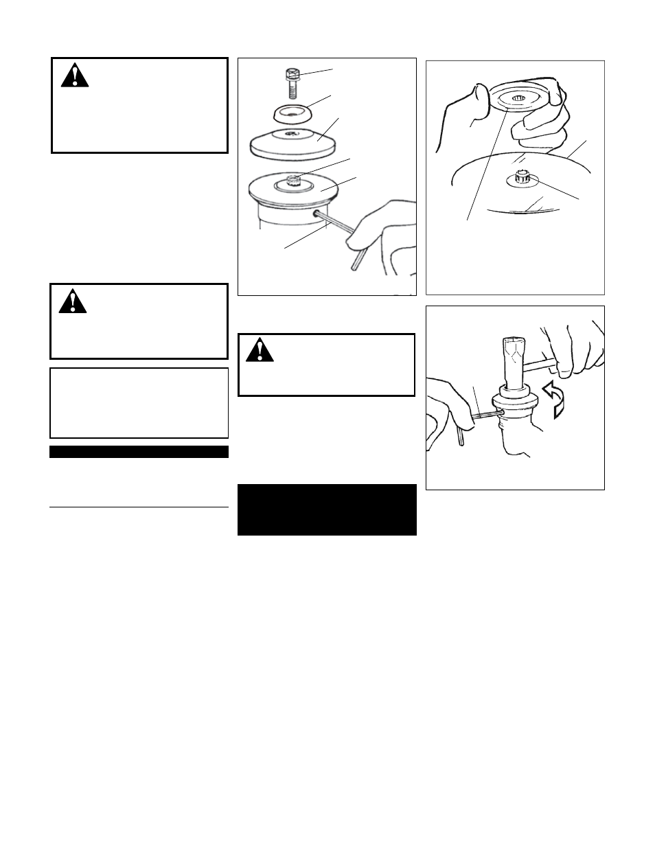
Turn the unit upside down so the gear
1.
case output shaft is facing UP and
remove the shaft bolt, bolt guard and
holder B from the gear case shaft.
Align the hole in blade holder A with
2.
the matching hole in the gear case
flange and then temporarily lock the
output shaft by inserting a hex wrench
through both holes.
Fit the blade over the flange on holder A.
3.
Shaft Bolt
Bolt Guard
Holder B
Gear Shaft
Holder A
Temporarily lock the output shaft by
inserting a hex wrench through both holes
Install blade holder B on the output shaft.
Blade
Hex Wrench
Blade Holder B
Tighten the assembly
(blade not shown for
clarity)
Output
Shaft
CAUTION!
Install the blade so its printed surface
is visible to the operator when the
brushcutter is in the normal operating
position.
WARNING!
7KHEODGHPXVW¿WÀDWDJDLQVW
WKHKROGHUÀDQJH7KHEODGHPRXQWLQJ
hole must be centered over the raised
boss on blade Holder A.
WARNING!
+ROGHU%PXVW¿WÀXVKDJDLQVW
the blade and the splines engaged to
the output shaft.
WARNING!
Do not attach any blade to
a unit without proper installation of
all required parts. Failure to use the
proper parts can cause the blade to
À\RIIDQGVHULRXVO\LQMXUHWKHRSHUDWRU
and/or bystanders.
The unit should now be
completely assembled and ready
for use with a blade.
IMPORTANT!
Discard blades that are bent, warped,
cracked, broken or damaged in any way.
Use a sharp blade. A dull blade is more
likely to snag and thrust.
Install blade holder B on the output
4.
shaft.
Install the bolt guard and then the blade
5.
retaining bolt. Using the combination
spark plug wrench/screwdriver, tighten
the bolt firmly in a counter-clockwise
direction.
Remove the hex wrench.
6.
Using the combination spark plug wrench/
VFUHZGULYHUWLJKWHQWKHEROW¿UPO\LQD
counter-clockwise direction.
Installing Brushcutter Blade
9
Assembly (continued)