Low saturation voltage transistor generation map – Sanyo EP92H User Manual
Page 18
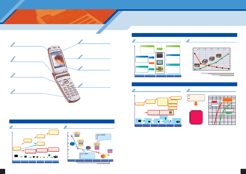
SANYO supplies high-performance GaAs switching ICs that feature the industry's smallest package size and smallest number
of external components. SANYO discrete devices have been always leading the cell phone and mobile equipment markets.
SANYO is also developing devices that support the need for higher speeds and larger data capacities for image and video data
due to the inclusion of high pixel count cameras in this equipment.
35
34
Handling More Data Even Faster. Supporting Needs for Higher Performance with
Peripheral Components
SANYO's Lineup of High-Reliability
Discrete Devices
Low noise, High gain transistors
(fT=20 GHz)
SBFP405M, SBFP420M...etc.
Low insertion loss MMIC /
High isolation MMIC
SBS804...etc.
ECH8601, FTD2017A...etc.
VEC2301, SCH2602, ECH8603
MCH6307...etc.
TF218TH, TF208TH, TF202(SSFP)...etc.
EC3H02B, 2SC5538, 2SC5539...etc.
EC2D01B, SB0203EJ...etc.
Low phase noise transistors
EC3H02B, EC3H09B...etc.
Precise interface control MOSFETs
5LN01S, 5LP01S
MCH6614(2 in 1)...etc.
MCH5809, CPH5809(MOS + SBD)...etc.
Bipolar Transistor for LNA
Devices for Li-ion batteries
Junction FETs for ECM
Devices for CCD camera module
Bipolar transistor for VCO
Power management switches
SPM3211, SPM3212,
SPM3215, SPM3218...etc.
Ultralow on-resistance MOSFET series
Ultralow on-resistance MOSFET series
Schottky barrier diodes
Schottky barrier diodes
Ultrathin package: VTFP
Ultrahigh-frequency transistors
Complex devices
GaAs MMIC products for antenna
switches and local switches
Transistors for LCD backlight circuits
Ultralow on-resistance MOS devices for power management
Low VF/IR Schottky barrier diodes for power management
Ultralow on-resistance MOS device generation map
Low and medium output MOS device development roadmap
RON
¥
A [m
Ω
¥
mm
2
]
Cell density [Mcell/inch
2
]
RDS(on)
2.5 m
Ω
10
µ
m
1.1
µ
m
100
90
80
70
60
50
40
30
20
10
0
270
240
210
180
150
120
90
60
30
0
J5
T1
T2
T3
T4
T5
1998
2000
2002
2004
2005
2006
5
µ
m
0.8
µ
m
3
µ
m
0.55
µ
m
2.5
µ
m
0.35
µ
m
1.8
µ
m
0.25
µ
m
1.3
µ
m
0.18
µ
m
Cell pitch
Design rule
Low voltage
drive
VGS=4V
2.5V
1.5V
1.8V
Low VF/IR Schottky barrier diode development roadmap
30V 1A 0.45V
30V 0.7A 0.55V
PCP
15V 1A 0.4V
CPH
Performance
New generation
4pin ECSP
1999
2000
2001
2002
2003
2004
2005
2006
2007
[Year]
[Year]
Befor
1998
15V 1A 0.4V
MCPH
15V 1A 0.4V
SCH
ECH
15V 2A 0.4V
×
2
SOP-WL
Parallel, Twin SBD
MOS + SBD
TR + SBD
Compound
product
deployment
RDS(on)
15 m
Ω
RDS(on)
5.3 m
Ω
RDS(on)
3.8 m
Ω
RDS(on)
2.8 m
Ω
Cell density
Low capacity
process
RDS(on)
3.2 m
Ω
RON ¥ A
VF – I comparison data for earlier and low-VF devices Schottky barrier diodes
2003
2004
2005
2006
2007
High
performance
High
performance
Miniaturization
T4: 16 million cells per
square inch)
Wireless package
High side switches
Miniaturization
Added functionality
Reduced on-resistance/reduced voltage drive
Multi Function
Multi Function
Differentiation
Device
Device
MOSFET
MOSFET
¥ Deployment to miniature thin-form
products; VEC8, SCH6, ECSP
¥ Wireless package technology
ECH8, TSSOP-WL, FlipFET
¥ Higher power and lower cost
ExPD
¥ Built-in driver MOSFETs
¥ Trench low side
¥ Back gate switches for lithium
battery charging and discharging
¥ High side switches and condenser
microphones for cell phones
ExPD
¥ Low Side
¥ Drivers (high voltage/
low voltage)
¥ PicoLogic
TM
SB10-015C
SBS010M
Reduced by
0.2 V
I
F
-V
F
(Comparison with earlier SANYO products)
10
1.0
0.1
0.01
I F
[A]
VF [V]
0
0.1
0.2
0.3
0.4
0.5
0.6
0.7
Contributes to
in end products!
Low forward voltage
Miniature thin-form
package
New Product
Earlier Product
1st Generation
SBD
2nd Generation
Low V
F
+ Ti barrier
3rd Generation
Low V
F
- high-density
sub + Ti barrier
Low I
R
- high-density
sub + MO barrier
Low V
F
- Low I
R
New structure Schottky
barrier diode
150¡C
guaranteed
Wireless
Low VF - Low IR
Barrier metal
inspection
¥ Trench structure (T4) -> (T5)
¥ Increased speed and further
improved ultralow on-resistance
¥ Reduced voltage drive
(from 1.5 to 1.2 V)
¥ Shorter turnaround times
(fewer masks)
¥ Trench structure (T3/4) deployment
(T3: 10 million, T4: 16 million cells per
square inch)
¥ Shallow trench technology established
¥ High ESD resistance technology
established
¥ Lineup covering 12 to 200 V
¥ Low on-resistance process
established (T2 trench process)
increased
efficiency,
miniaturization,
and thinner
form factors
[Year]
R
CE
(sat) - m
Ω
1998
1999
2000
2001
2002
2003
2004
2005
2006
[Year]
Before
1997
160
140
120
100
80
60
40
20
Cell density
65Kcell/inch
2
RCE(sat)
140m
Ω
RCE(sat)
70m
Ω
RCE(sat)
50m
Ω
RCE(sat)
35m
Ω
Cell density
144cell/inch
2
Cell density
144cell/inch
2
Low resistance
of collector layer
50%
down
30%
down
30%
down
hFE=100 to 400, Width=300
hFE=200 to 560, Width=360
hFE=250 to 400, Width=150
Very low saturation voltage
High switching speed
Small and high power package
Ultra low saturation voltage
Narrow width of hFE
High switching speed
Ultralow saturation voltage transistor development roadmap
High
performance
Small
Low cost
High performance
PCP
CPH
MCPH ECH SCH
2002
2003
2004
2005
2006
2007
Performance/functionality — Miniaturization
ECSP
SOP-WL
High performance
High performance
1st Generation
MBIT
2nd Generation
MBIT-II
3rd Generation
MBIT-III
4th Generation
High-speed SW
MBIT-IV
MBIT-IIs
(Single-layer
electrode)
High hFE support - ECSP
¤
package
High voltage (80 V and over)
- High output support
PicoTR surface mounting
package deployment
Support for hFE1 ranking
MCPH, PCP, and TP leads
Package deployment -
Compound CPH deployment
Low saturation voltage transistor generation map
LCD backlight ultralow saturation voltage transistors
High performance/
low cost