Instruction manual – StarTech.com PCI2S650PW User Manual
Page 7
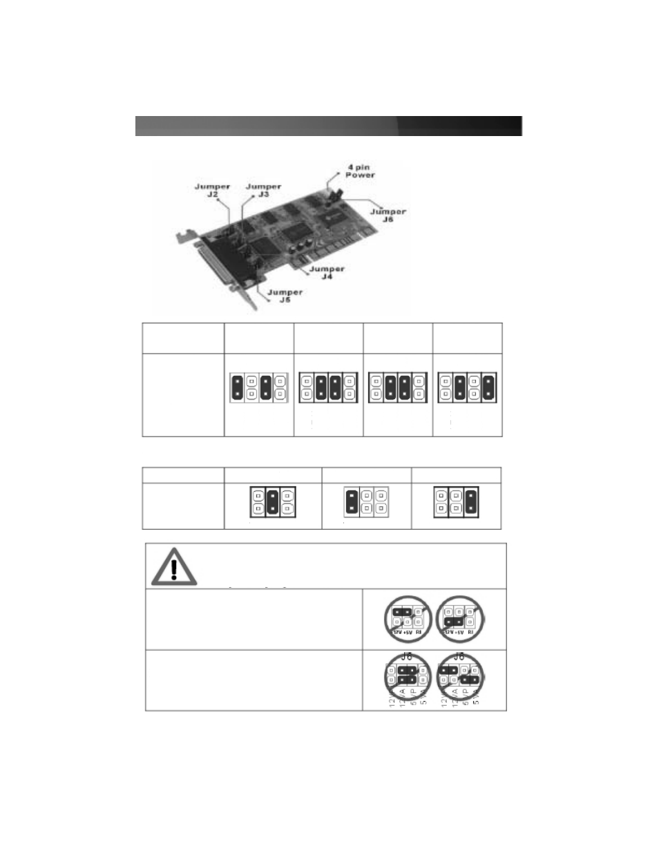
Configuring the Jumpers: PCI4S650PW
Instruction Manual
4
Failure to observe these warnings could cause damage to
the serial card, computer, and peripherals.
Do not set any of the jumpers J2-J5 to supply
both 5v and 12v power at the same time.
Ensure jumper caps are placed vertically in line
with the markings on the board, not “across”
settings.
The card uses jumpers to set
internal and external power
voltages, and to configure
which serial ports will receive
5v, 12v, or RI signal
(unpowered) through the 9th
pin.
J6: Sets internal (bus) voltage
and the external power drawn
through the SP4 power
connector (external)
J2 thru J5: Sets voltage for
each individual DB9 port
12VP
12V
A
5 VP
5 V
A
12VP
12V
A
5 VP
5 V
A
12VP
12V
A
5 VP
5 V
A
12VP
12V
A
5 VP
5 V
A
J6
J6
J6
J6
*Please select 5V, 12V, or RI Signal for COM1~COM4 using J2~J5
Power
Supply
Int5V
Int12V
Int5V
Ext12
Ext5V
Int12V
Ext5V
Ext12V
Jumper Setting
J2 - J5
Jumper Setting
+12W +5V RI
+12W +5V RI
+12W +5V RI
5V
12V
RI