7 hardware description, 1 connections, 2 buttons and controls – Siemens CMTC1913 User Manual
Page 8: Hardware description, Connections, Buttons and controls, 7hardware description
Hardware Description
8
Building Technologies
CMTC1713_1913 User Manual
Fire Safety & Security Products
19/12/2008
7
Hardware Description
7.1
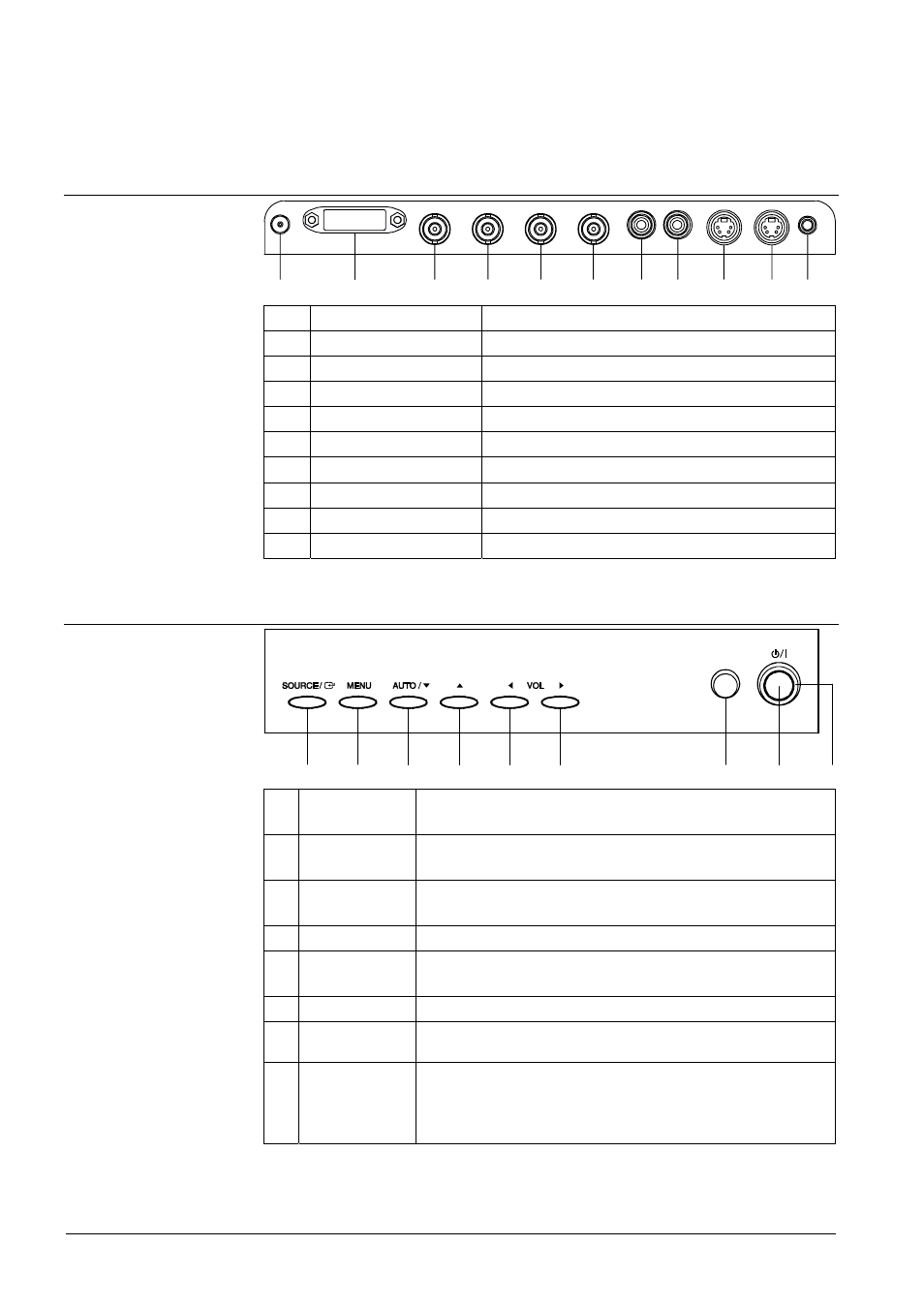
Connections
1
2
3
4
5
6
7
8
9
10
11
1
DC 12V IN
DC power input
2
DVI IN
PC signal input
3
VIDEO 1 IN
Composite signal input for AV1
4
VIDEO 1 OUT
Video looping output for AV1
5
VIDEO 2 IN
Composite signal input for AV2
6
VIDEO 2 OUT
Video looping output for AV2
7, 8
AUDIO IN (L+R)
Stereo audio signal input for video
9
S-VIDEO IN
Y/C separated signal input
10
S-VIDEO OUT
Y/C separated signal looping output
10
PC STEREO IN
Stereo audio stereo input for PC
7.2
Buttons and controls
1
2
3
4
5
6
7
8
9
1
SOURCE
Selects input source (AV1, AV2, S-Video, DVI-D, DVI-A)
In OSD menu: Enters sub menu
2
MENU
Enters and exits the OSD menu [J 11]
In OSD menu: Exit sub menu
3
AUTO / ▼
Auto geometry adjustment (only in DVI-A mode)
In OSD menu: Moves downwards in the menu
4
▲
In OSD menu: Moves upwards in the menu
5/6 ◀ VOL ▶
Adjusts the volume
In OSD menu: Adjusts menu settings or enters/exits the submenu
7
IR SENSOR
Remote control sensor
8
POWER
SWITCH
Turns the power ON or OFF
9
POWER LED
Shows the monitor power status
(Green = The power is turned ON; Red = The power is turned
OFF)
See also chapter Power management [J 9]