1 overview – Sony DX4 User Manual
Page 40
AR-B1474 User¡
¦s Guide
5-2
5.2.1 Overview
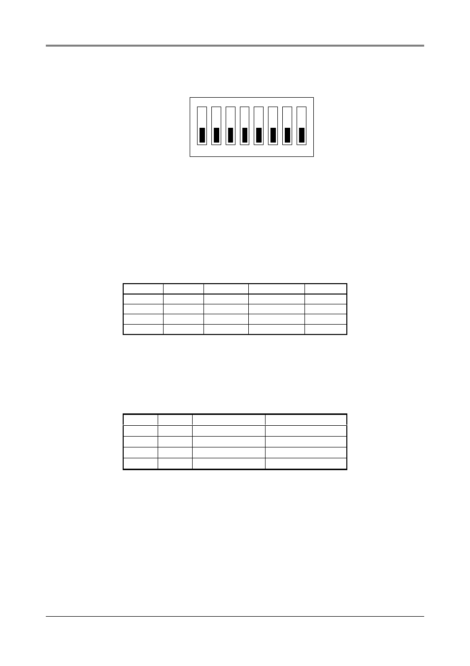
There is 1 DIP Switch located on the AR-B1474. It performs the following functions:
ON
1
2
3
4
5
6
OFF
7
8
Figure 5-2 SW1: Switch Select
SW1-1 & SW1-2 Set the base I/O port address
SW1-3 & SW1-4 Set the starting memory address
SW1-5 & SW1-6 Set the drive number of solid state
disk
SW1-7 & SW1-8 Set the used ROM memory chips
5.2.2 I/O Port Address Select (SW1-1 & SW1-2)
SW1-1 & SW1-2 are provided to select one of the four base port addresses for the watchdog timer and the solid
state disk. The AR-B1474 occupies 6 I/O port addresses. Followings state selections of base port address.
SW1-1
SW1-2
Base Port
Solid State Disk Watchdog
OFF (*)
OFF
210h
210h-213h
214h-215h
ON
OFF
290h
290h-293h
294h-295h
OFF
ON
310h
310h-313h
314h-315h
ON
ON
390h
390h-393h
394h-395h
Table 5-1 I/O Port Address Select
5.2.3 SSD Firmware Address Select (SW1-3 & SW1-4)
The AR-B1474‘ s SSD firmware occupies 16KB of memory. SW1-3 & SW1-4 are used to select the memory base
address. You must select an appropriate address so that the AR-B1474 will not conflict with memory installed on
other add-on memory cards. Additionally, be sure not to use shadow RAM area or EMM driver’ s page frame in this
area.
SW1-3
SW1-4
SSD BIOS Address Bank Memory Address
OFF (*)
OFF
C800:0 (8KB)
CA00:0 (8KB)
ON
OFF
CC00:0 (8KB)
CE00:0 (8KB)
OFF
ON
D000:0 (8KB)
D200:0 (8KB)
ON
ON
DC00:0 (8KB)
DE00:0 (8KB)
Table 5-2 SSD Firmware Address Select
If you are not going to use the solid state disk (SSD), you could use JP7 to disable the SSD BIOS. The AR-B1474
will not occupy any memory address if the SSD BIOS is disabled.
If you are going to install the EMM386.EXE driver, please use the [X] option to prevent EMM386.EXE from using
the particular range of segment address as an EMS page which is used by AR-B1474. For example, write a
statement in the CONFIG.SYS file as follow: (If the memory configuration of AR-B1474 is C800:0)
DEVICE=C:\DOS\EMM386.EXE X=C800-CFFF