Silex technology SX-550 User Manual
Page 2
OEM Interface
The OEM interface allows OEMs to add functionality via a
daughtercard. Power is also input via this header. This is a 40-
pin 0.05” pitch surface-mount header
Pin
Signal
Pin
Signal
1
TPRX+
2
TPTX+
3
TPRX-
4
TPTX-
5
SWITCH
6
LED_1
7
AVDD
8
+3.3VDC
9
UART0_RXD
10
GPIO_9
11
UART0_TXD
12
GPIO_10
13
GND
14
+3.3VDC
15
UART0_RTS
16
UART0_CTS
17
UART1_RTS
18
UART1_CTS
19
GND
20
GND
21
UART1_TXD
22
UART1_RXD
23
GND
24
RESET_N
25
SPI_CS
26
SPI_CLK
27
+3.3VDC
28
GND
29
GPIO_1
30
SPI_SDO
31
GPIO_2
32
SPI_SDI
33
+3.3VDC
34
GND
35
GPIO_3
36
GPIO_4
37
GND
38
GND
39
GPIO_5
40
GPIO_6
Specifications
Serial Ports
Two serial UART ports are be
accessible via the OEM header.
General Purpose I/O Signals
8 of the general purpose signals
of the CN210 Processor are
accessible via the OEM header.
They can be used for driving
LED's, receiving switch input or as
general purpose signals that allow
the user to monitor or control via
the silex software interface.
External pull-ups are required for
customization.
Power Input
Power is input to the main module
via the OEM header. +3.3VDC +/-
10% is supplied through this
header.
Power Consumption
Wireless LAN power consumption
900mA for maximum transmit.
.
Environmental Temperature
•
Operating Temperature: 0
°
to 50
° C
•
Storage Temperature: -20
°
to +70
° C
•
Maximum temperature
change per hour: 20
° C
Relative Humidity
•
Operating: 10% to 90% non-
condensing
•
Storage: 10% to 90% non-
condensing
Altitude
•
Operating: 3.1 km
•
Storage: 9 km
Shock
•
MIL-STD-202F (Method
213B) to 50 G's
Vibration
•
MIL-STD-202F (Method
204D) to 15 G's
Standards Compliance
•
RS232, serial interfaces
•
802.11 a/b/g for the wireless
version
•
802.3i (10Base-T) and
802.3u (100Base-TX)
Ethernet
•
RFC 2217
Ordering Information
For your specific configuration and its corresponding part number,
call silex at 1-866-765-8761 (U.S. toll-free) or +1 801-748-1199
(other countries).
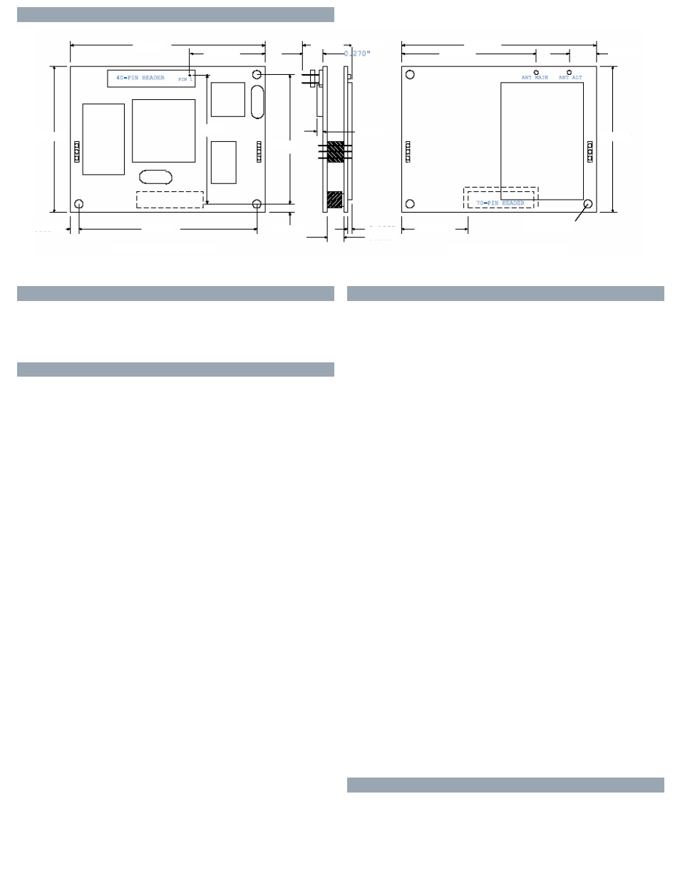
silex SX-550 Module Diagram
0.875"
2.346"
0.570"
0.270"
0.140"
1.660"
2.346"
0.215"
1.750"
0.087" DIA
6 PLACES
0.100"
0.118"
0.770"
1.500"
1.580"
0.085"
2.176"
1.750"
0.85"
CPU BOARD - BOTTOM VIEW
WIRELESS LAN - TOP VIEW
Port 1 supports Transmit Data,
Receive Cata, Clear to Send, and
Request to send. 3 of the GPIOs
can be configured for use as the
Data Terminal Ready, Dataset
Ready, and Data Carrier Detect
modem signals.
Port 2 is dedicated for as a
console port for management
and configuration purposes.
Technical information and specifications are subject to change without notice. ©2008 Silex Technology, Inc.