SpeakerCraft Home Theater Server User Manual
Page 12
8
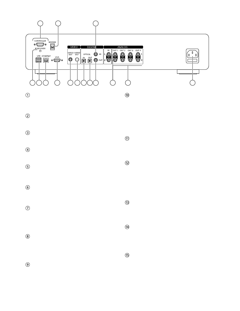
REAR VIEW
6
12
13
14
15
10
9
8
7
5
4
3
1
2
11
IR RECEIVER
The IR Receiver connection allows remote control
information to be carried from other devices directly into
the Audio Server.
CONTROLLER
The Controller port provides serial communication with
supported devices.
UsB
Allows the Audio Server to communicate with supported
USB devices.
ETHERNET
The Ethernet port is used to connect the Audio Server to
a high speed Internet connection.
VGA
The VGA connector may be used to connect a VGA
monitor or a suitable Plasma screen for displaying the TV
user interface.
MODEM
The Modem port can be used to connect the Audio
Server to a standard analog telephone line for Internet
access.
VIDEO OUT
Connect the composite Video Out of the Audio Server
to the composite input of a suitable PAL/NTSC TV
(depending on the supplied configuration) to display
the TV User Interface. You may also need to switch the
TV to the relevant AUX input to display the picture.
s-VIDEO OUT
Connect the S-VIDEO output of the Audio Server to the
S-VIDEO input of a suitable PAL/NTSC TV (depending
on the supplied configuration) to display the TV User
Interface. You may also need to switch the TV to the
relevant AUX input to display the picture.
DIGITAL OPTICAL IN
High quality recordings can be made onto the hard
disk of the Audio Server using an optical connection
from a suitable device (such as Minidisc or DAT). (To be
supported in future software releases).
DIGITAL OPTICAL OUT
The digital optical output can be used to transmit high
quality audio to a device with a digital optical input (D/A
converter, A/V amplifier etc.) using an optical fiber cable.
The advantage of using the optical output is that it has
low signal loss due to cables and is completely isolated
from the ground loop. The audio output of the Digital
Optical Out connector is the same as the audio output of
the Analog Audio Out 1 connector. This output may not
be used for making a digital copy of your media.
DIGITAL IN - COAXIAL
High quality recordings can be made onto the hard
disk of the Audio Server using a coaxial connection
from a suitable device (such as Minidisc or DAT). (To be
supported in future software releases).
DIGITAL OUT - COAXIAL
By connecting this jack to a digital audio component
(D/A converter, A/V amplifier etc.), digital signals from
the Audio Server can be transmitted directly from the
system without first being converted to analog. The
audio output of the Digital Coaxial Out connector is the
same as the audio output of the Analog Audio Out 1
connector. This output may not be used for making a
digital copy of your media.
ANALOG IN
Analog sources (such as cassette or vinyl LP) may be
recorded onto the hard disk of the Audio Server using
this connection. (To be supported in future software
releases).
ANALOG OUT 1,2,3,4
The Audio Server is a multiroom device allowing you to
listen to different music in up to four different rooms
all at the same time (depending on the configuration
purchased). Each analog output should be connected to
the input jacks of a pre-amplifier.
MAINs
Connect the supplied mains lead to this connector to
provide power to the unit.