5 the remote control, Compact, 10 the multifunctional contact – Studer Innotec XPC 2200-48 User Manual
Page 17: 11 the temperature sensor, 1 remote control plug-in, 2 power monitor, Xp-compact, User manual xp-compact v5.1 e 16
STUDER Innotec
XP-COMPACT
User manual
XP-COMPACT V5.1 E
16
4.10 The Multifunctional Contact
In the XP-COMPACT there is a built-in power relay. The potential-free change-over contact (NO –
NC) of this power relay is connected to the screw terminal AUX CONTACT.
Maximum Contact load:
230Vac /12Vdc/24Vdc/16Amp
60Vdc/3 Amp. !
The contact is activated when the XP-COMPACT is halted or by a fault condition, or by a normal
manual stop done by pushing push-button 19.
This auxiliary contact can be freely programmed for any displayed functional status through the
remote control (refer to chap.5)
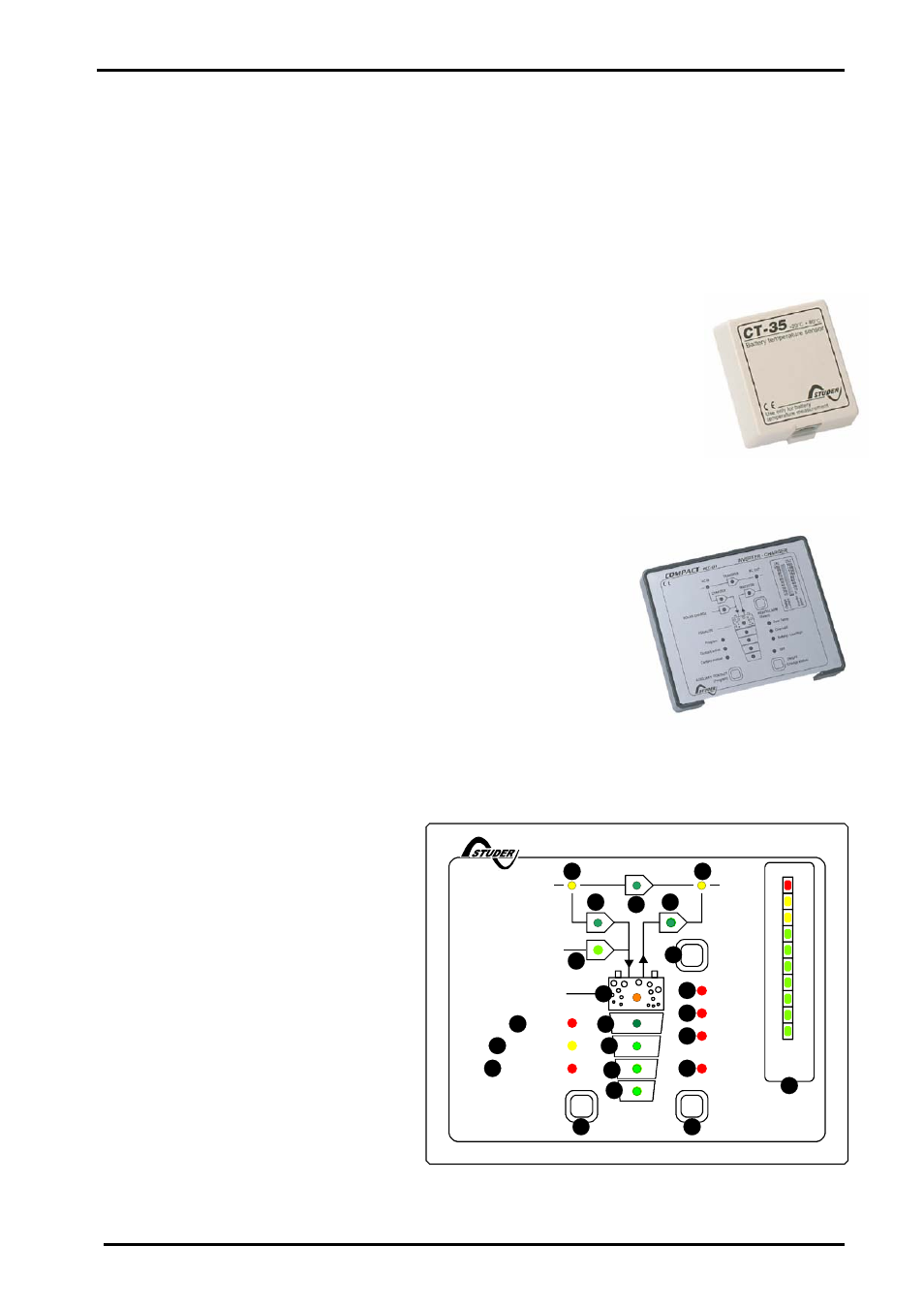
4.11 The Temperature sensor
Operating voltage of lead-acid batteries change depending on the tempera-
ture. To correct the operating voltages according to the actual temperatures, a
temperature sensor can be connected to the COMPACT.
The compensation through the sensor is –3mV/°C/Cell.
Order Number: CT-35
Dimensions: H x B x T / 58 x 51.5 x 22mm
5 The Remote Control
As an option a Remote Control can be connected to the XP-
COMPACT through a standard supplied 20m long cable. It can be
extended to 40m.
The Remote Control is suitable for surface mounting on the wall or
on to a switch board. It is fixed with 4 screws.
All operating controls and displays except from level adjustment
are available on the Remote Control. Several extra features are
implemented in the remote control:
A charging current monitor (25)
Output power monitor (25)
The battery status monitor
Auxiliary contact programming
Battery voltage level adjustment
Remote Alarm contact and command
5.1 Remote control plug-in
The remote is delivered with a 20m long
cable and can be connected or discon-
nected at any time while the main unit is
running (hot plug).
The remote control can be mounted with
the frame or directly on a board. The
screws are not supplied.
5.2 Power
monitor
The instantaneous power of the inverter
in % off Pnom or the charging current is
continuously displayed on LED lines
(25).
160
OFF
AC OUT
Over Temp.
Overload
AC IN
SOLAR CHARGE
Contact manual
Contact active
Program
COMPACT
AUXILIARY CONTACT
ON/OFF
INVERTER - CHARGER
(Select)
RCC-01
INVERTER
CHARGER
(Program)
(Change status)
Battery
Low/High
RESET
ALARM
10
20
30
40
50
60
70
80
90
100
TRANSFER
Ch
a
rg
e
r
In
v
e
rte
r
5
10
20
40
60
80
100
130
160
A
%
EQUALIZE
1
15
16
17
18
19
2
3
21
4
5
6
13
12
11
10
20
25
8
7
9
14