Caution – S&S Worldwide Motorcycle Accessories User Manual
Page 7
D.
With key in shaft, insert into respective tapered hole in
flywheel and check to see that key does not bottom in
groove. If key bottoms out, file flat side of key, not
rounded side, until shaft with key in place fits in
flywheel without bottoming out. Check crankpin and
crankpin key also.
E.
Reclean mainshaft tapers, crankpin and flywheel tapers
with lacquer thinner.
F.
Assemble mainshafts in respective flywheels. Coat taper
and threads of each shaft with green Loctite
®
during
assembly. Install crankpin in camside flywheel using
Loctite
®
also. Tighten crankpin nuts to 290-310 ft. lbs.
Tighten pinion and sprocket shaft nuts to 340-360 ft. lbs.
G.
After camside flywheel, pinion shaft and crankpin are
assembled, blow air through pinion shaft oil feed
hole to check for blockage or misalignment of oil
feed passages.
Partially or completely blocked oil feed passageways may
cause irreversible damage to connecting rod bearings and
other engine components.
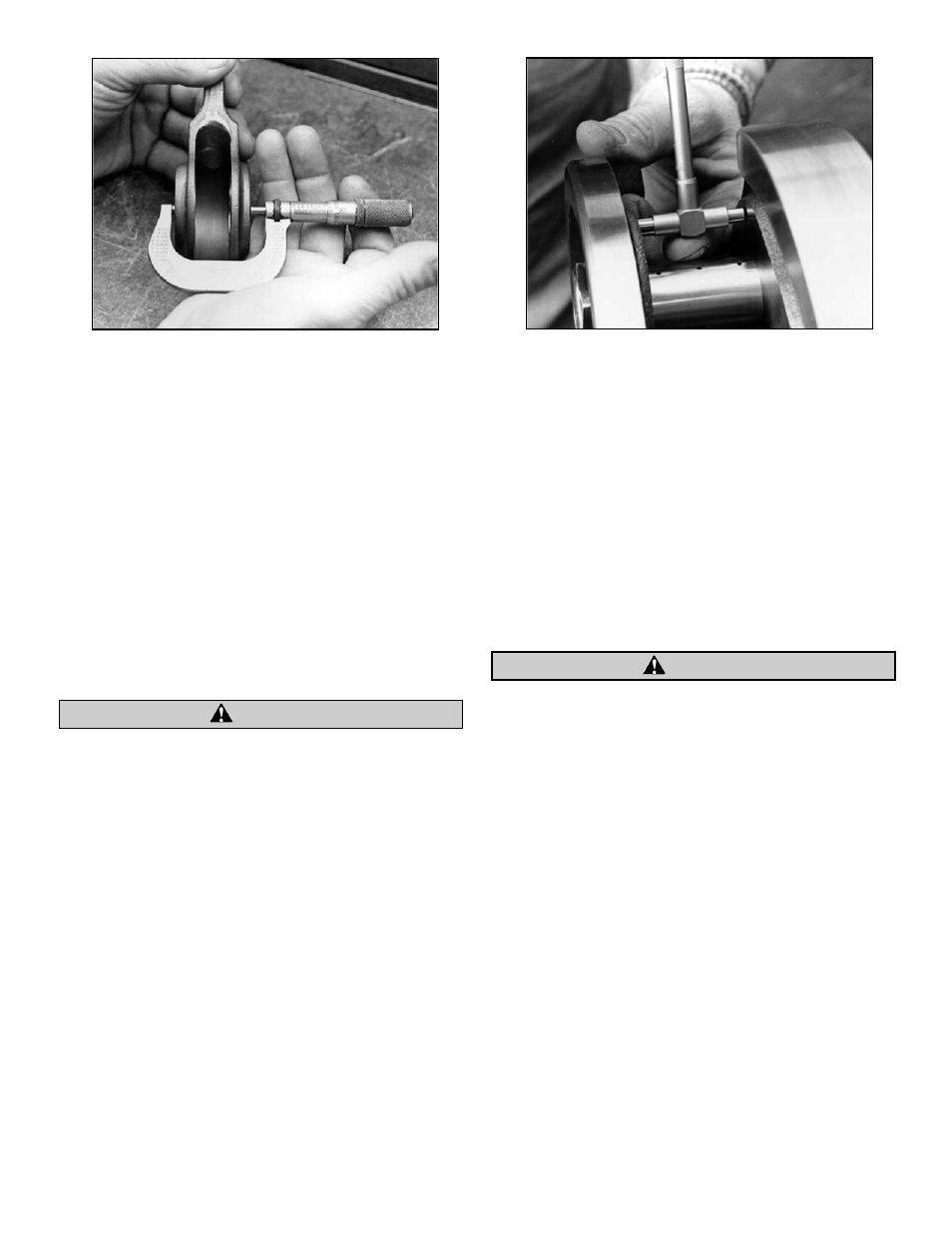
H.
Measure width of female rod on crankpin end. See
Picture 7. Measurement should be 1.481" to 1.483".
I.
A pre-assembly connecting rod side play check should
be done before final assembly to determine if
connecting rod side play will fall within the specified
.015"-.035" range when crankpin nuts are final
tightened. Assemble left and right flywheels on
crankpin without rods. Moderately snug crankpin nuts.
Do not worry about flywheels being true. Measure
distance between connecting rod thrust pads on
flywheels. See Picture 8. Rod side play will be reduced
by about .015" when crankpin nut is final tightened.
Therefore, distance between flywheel thrust pads as
measured in this check must be .030"-.050" greater than
female rod width measured in Step H. For example, if
female rod measures 1.482", the distance between
flywheel pads must be 1.512"-1.532". If difference
between pad to pad distance and female rod width is
less than .030", female rod must be surface ground on
sides to provide more clearance. Take equal amounts
off
each side if more than .010" is to be removed. If more
than .050" must be removed from female rod width or
if difference between pad to pad distance and female
rod width is greater than .050" a different crankpin
should be tried. If there is too little or too much
connecting rod side play, and different crankpins do not
correct problem, contact S&S
®
.
NOTE: S&S recommended rod side play is .015" to .035". If
material is removed from sides of female rod, overall width of
bearing cages must be reduced so bearings and cages are free to
float with rods without contacting flywheel thrust pads. Bearing
cage side clearance of .008" to .020" less than rod width is
recommended.
●
Incorrect connecting rod side play may cause excessive rod
side thrusting and potential damage to rods, flywheels and
other engine components.
●
Connecting rod bearing and cage assemblies that are wider
than female rod may become damaged upon contact with
flywheel thrust pads. Abrasive particles from damaged rod
bearings may circulate in oil and cause damage to other
engine parts.
J.
Finish assembling flywheels and rods.
K.
Check flywheel assembly for run out by placing ends of
mainshafts between centers. Place dial indicators on
bearing surfaces of mainshafts. See Picture 9. True
wheels as needed. S&S trues flywheel assemblies to
.0005" or less runout on either mainshaft bearing
surface. However Harley-Davidson
®
factory specs call for
.001" runout and this is acceptable.
NOTES:
●
When truing flywheels, runout measurements must be taken
on mainshaft bearing surfaces. Do not take measurements
on flywheel rims. Flywheel rim will show runout that is not
a valid indication of mainshaft concentricity.
●
Do not install flywheels and final assemble crankcases until
clearances are checked in Step 9.
7
Picture 7
Picture 8
CAUTION
CAUTION