Sanus Systems VMCT User Manual
Page 2
CSAV, Inc. and its affiliated corporations and subsidiaries (collectively, “CSAV”), intend to make this manual accurate and complete. However, CSAV makes no claim that the information contained herein
covers all details, conditions, or variations. Nor does it provide for every possible contingency in connection with the installation or use of this product. The information contained in this document is subject to
change without notice or obligation of any kind. CSAV makes no representation of warranty, expressed or implied, regarding the information contained herein. CSAV assumes no responsibility for accuracy,
completeness or sufficiency of the information contained in this document.
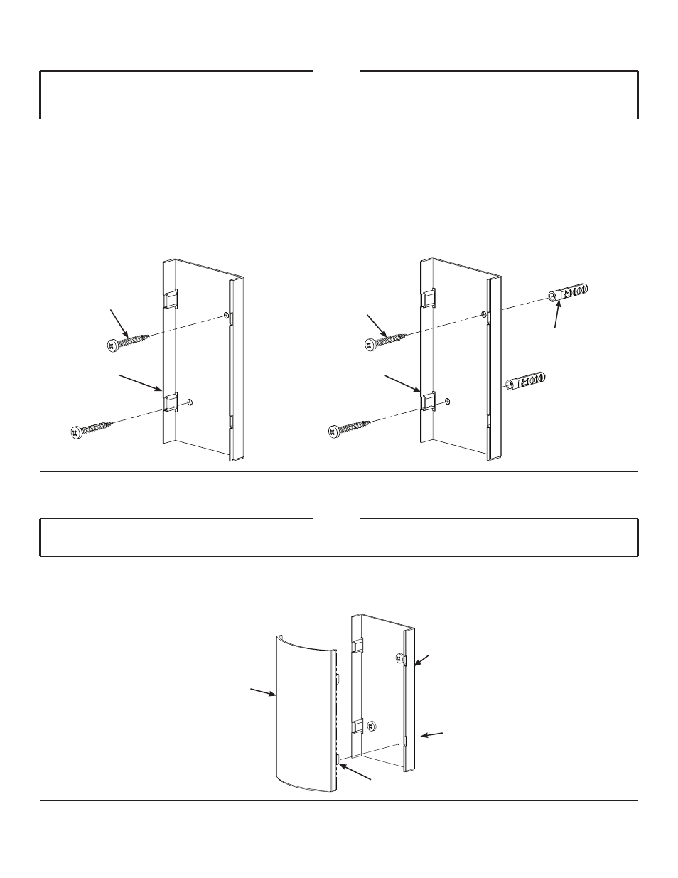
Step 1: Attach Wall Plate
NOTE:
Do not overtighten the Wood Screws (C). Tighten the Wood Screws only until the Wall Plate (A) is pulled firmly
against the wall. If there is a layer of drywall or other material, this drywall or other material may not exceed 5/8
inch [15.8 mm] in thickness.
Orient the Wall Plate (
A) so that its flat side is against the wall as shown in Diagrams 1A and 1B and use the Wall plate as
a template to mark the two holes for the Wood Screws (
C) on the chosen stud. Drill two pilot holes using the 3/16 inch drill
bit; then, using the Wood Screws, secure the Wall Plate to the stud as shown in Diagram 1A.
If the VMCT is to be mounted between studs, drill two holes in the drywall or wall material using the 3/8 inch drill bit; then,
insert the Anchors (D) and secure the Wall Plate as shown in Diagram 1B
Diagram 1A
Diagram 1B
A
A
C
C
D
Step 2: Wire Management and Cover Installation
NOTE:
Make sure all wires and cables are between the right and left edge of the Wall Plate (A) prior to installing the
Cover (B).
Press fit the Cover (
B) onto the Wall Plate (A) so each Tab on the Cover fits into each Slot in the Wall Plate as shown in
Diagram 2.
Diagram 2
A
B
Tab
Slot