SMSC USB464 User Manual
Page 20
High Speed Inter-Chip USB 2.0 Hub and Flash Media Controller
Datasheet
Revision 1.0 (06-01-09)
20
SMSC USB4640/USB4640i
DATASHEET
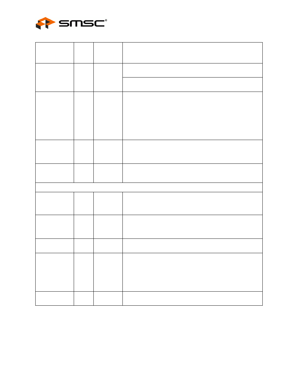
GPIO2 /
RXD
36
I/O6
This pin may be used either as input, edge sensitive interrupt input,
or output. Custom firmware is required to activate this function.
This signal can be configured as input to the RXD of the internal
UART. Custom firmware is required to activate this function.
GPIO10
(CRD_PWR)
35
I/O200
Card power drive: 3.3 V (100 mA or 200 mA)
This must be the only FET used to power devices. Failure to do this
will violate voltage specifications on device pins. If this pin is not
being used as a card power pin, this pin may be used either as input,
edge sensitive interrupt input, or output (GPIO).
Please see
Section 8.4.2.3, "A4h-A5h: Smart Media Device Power
for more information.
nRESET
38
IS
RESET input
The system uses this active low signal to reset the chip. The active
low pulse should be at least 1
μs wide.
TEST
40
I
TEST Input
Tie this pin to ground for normal operation.
DIGITAL / POWER / GROUND
CRFILT
15
VDD Core Regulator Filter Capacitor
This pin requires a 1.0
μF (or greater) ± 20% (ESR <0.1
Ω
) capacitor
to VSS.
PLLFILT
46
Phase-locked Loop Regulator Filter Capacitor
This pin requires a 1.0
μF (or greater) ± 20% (ESR <0.1
Ω
) capacitor
to VSS.
VDD12
41
1.2 V Power for HSIC pads and buffers
VDD33
5
12
16
25
34
48
3.3 V Power and Regulator Input
Please see
Chapter 10, "DC Parameters," on page 56
for more
information.
Pins 16 and 48 each require an external bypass capacitor of 4.7
μF
minimum.
VSS
ePad
The ground pad is the only VSS for the device and must be tied to
ground with multiple vias.
Table 6.1 USB4640/USB4640i Pin Descriptions (continued)
SYMBOL
48-PIN
QFN
BUFFER
TYPE
(
Table 6.2
)
DESCRIPTION