Sony Ericsson GS64 User Manual
Page 44
LZT 123 1836
44
5.8.2 Module On & Off Sequence
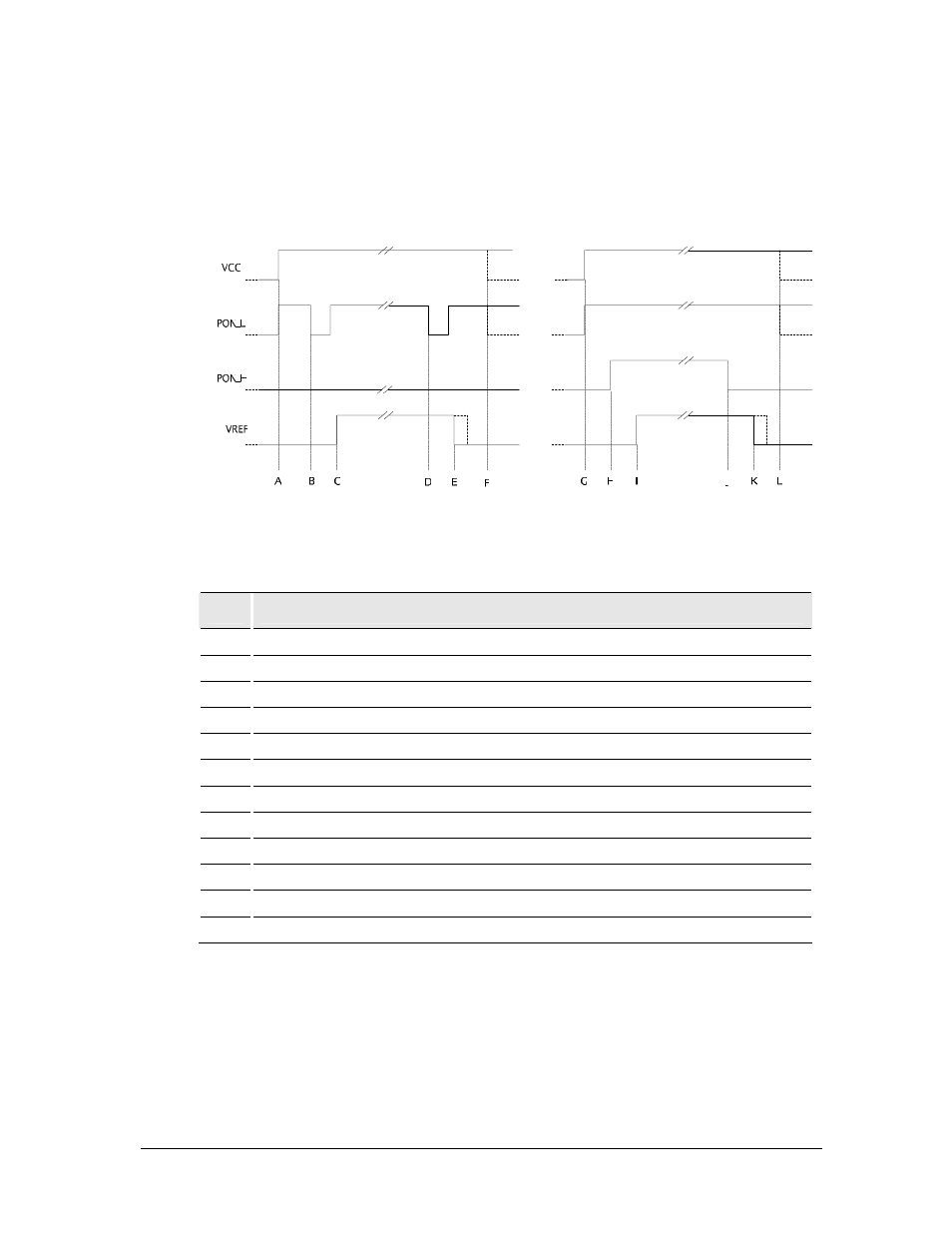
Figure 5.8-1 shows typical powering-on and powering-off sequences, using the two
optional hardware interfaces.
Figure 5.8-1 Typical Power-On & Power-Off Sequences
Event Description
A
VCC is applied to the module, PON_L is pulled high internally
B
PON_L is pulled low by the user application, initiating a power-on sequence
C
VREF presence indicates a successful power-on initialization
D
PON_L is pulled low by the user application, initiating a power-off sequence
E
VREF absence indicates network de-registration and shut-down complete
F
VCC can be safely removed
G
VCC is applied to the module, PON_H is pulled low internally
H
PON_H is pulled high & retained high, initiating a power-on sequence
I
VREF presence indicates a successful power-on initialization
J
PON_H is released, initiating a power-off sequence
K
VREF absence indicates network de-registration and shut-down complete
L
VCC can be safely removed