Electrical adjustments – Sony Ericsson CDP-CX220 User Manual
Page 19
– 19 –
Note:
A clear RF signal waveform means that the shape “
◊
” can be clearly
distinguished at the center of the waveform.
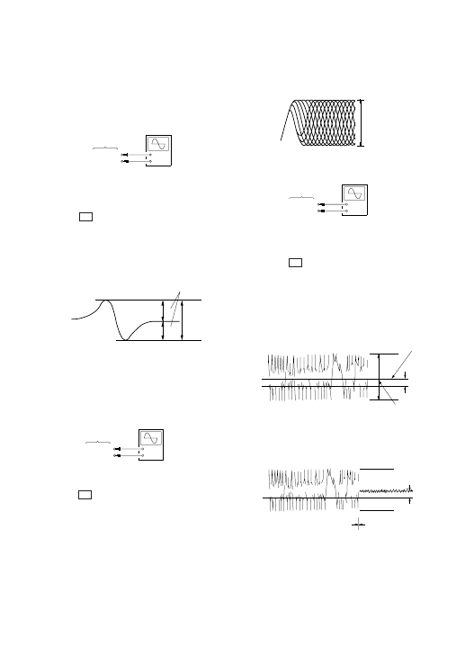
E-F Balance Check
Procedure :
1. Connect oscilloscpe to test point TP (TE) on BD board.
2. Connect the test point TP (ADJ) on MAIN board to the ground
with a lead wire.
3. Turn the
I/
u button on to set the ADJ mode.
4. Put disc (YEDS-18) in to play the number five track.
5. Press the
[GROUP 3]
button. (The tracking servo and the sled-
ding servo are turned OFF.)
6. Check the level B of the oscilliscope's waveform and the A
(DC voltage) of the center of the Traverse waveform.
Confirm the following :
A/B x 100 = less than ± 22%
7. Press the
[GROUP 8]
button. (The tracking servo and sled-
ding servo are turned ON.) Confirm the C (DC voltage) is
almost equal to the A (DC voltage) is step 6.
8. Disconnect the lead wire of TP (ADJ) connected in step 1.
SECTION 6
ELECTRICAL ADJUSTMENTS
Note:
1.
CD Block is basically designed to operate without adjustment. There-
fore, check each item in order given.
2.
Use YEDS-18 disc (3-702-101-01) unless otherwise indicated.
3.
Use an oscilloscope with more than 10M
Ω
impedance.
4.
Clean the object lens by an applicator with neutral detergent when the
signal level is low than specified value with the following checks.
S-Curve Check
Procedure :
1. Connect oscilloscope to test point TP (FE1) on BD board.
2. Connect test point TP (ADJ) on MAIN board to ground with
lead wire.
3. Turn
I/
u button on to set the ADJ mode.
4. Put disc (YEDS-18) in and playback.
Press the
[CHECK]
button.
5. Check the oscilloscope waveform (S-curve) is symmetrical be-
tween A and B. And confirm peak to peak level within 3 ± 1
Vp-p.
6. After check, remove the lead wire connected in step 2.
Note:
• Try to measure several times to make sure than the ratio of A : B
or B : A is more than 10 : 7.
• Take sweep time as long as possible and light up the brightness
to obtain best waveform.
RF Level Check
Procedure :
1. Connect oscilloscope to test point TP (RFO) on BD board.
2. Turn
I/
u button on.
3. Put disc (YEDS-18) in to play the number five track.
4. Confirm that oscilloscope waveform is clear and check RF sig-
nal level is correct or not.
BD board
TP (FE1)
TP (VC)
+
–
oscilloscope
S-curve waveform
symmetry
A
B
within 3
±
1 Vp-p
BD board
TP (RFO)
TP (VC)
+
–
oscilloscope
(AC range)
VOLT/DIV: 200 mV
TIME/DIV: 500 ns
level: 1.2 Vp-p
RF signal waveform
+0.25
–0.20
BD board
TP (TE)
TP (VC)
+
–
oscilloscope
Traverse waveform
Center of the waveform
B
A (DC voltage)
level: 1.3
±
0.6 Vp-p
0 V
Traverse waveform
C (DC
voltage)
0 V
Tracking servo
Sled servo
OFF
Tracking servo
Sled servo
ON