Caution – System Sensor INNOVAIR DH100LP User Manual
Page 6
D200-15-00 6 I56-0083-07R
DETECTOR
BOARD
7
6
4
(+) IN
(+) OUT
(+)
(+)
5
8
(–)
(–) IN
(–) OUT
1ST DETECTOR
IN LOOP DH100LP
(–)
RA400Z (OPTIONAL)
REMOTE ALARM LED
2.8 VDC NOM.
IN ALARM
DETECTOR
BOARD
7
6
4
(+) IN
(+) OUT
(+)
(+)
5
8
(–)
(–) IN
(–) OUT
LAST DETECTOR
IN LOOP DH100LP
(–)
RA400Z (OPTIONAL)
REMOTE ALARM LED
2.8 VDC NOM.
IN ALARM
E
O
L
R
STYLE D OPTIONAL WIRING
UL LISTED
COMPATIBLE 2-WIRE
CONTROL PANEL
ALARM
INITIATION
LOOP
(+)
(–)
EOL RESISTOR
SPECIFIED BY
PANEL MANUFACTURER
CAUTION
Do not loop wire under terminals when wiring detectors. Break wire runs to provide system supervision of connections.
1
2
3
4
5
3
4
5
Test +
Test / Reset –
Reset +
Test
Reset
RA +
RA –
DH100LP
RTS451/RTS451KEY
2
1
Alarm
LED
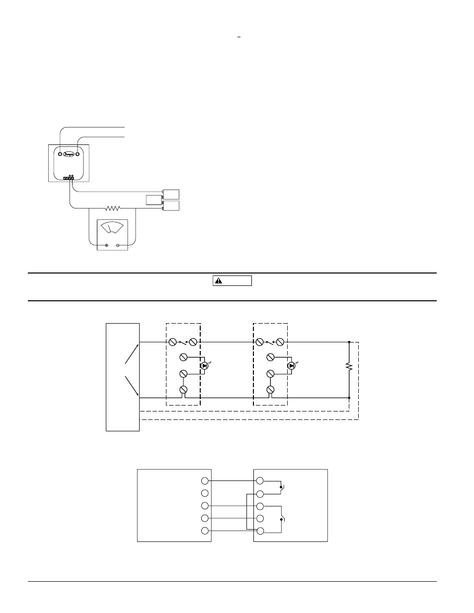
Figure 9. Wiring diagram for the DH100LP to RTS451/RTS451KEY:
Figure 8. System wiring diagram for 2-wire duct smoke detectors (detectors powered from initiating circuit):
A78-2696-00
the duct smoke detector housing, and the LOW side of the
transmitter to the exhaust tube of the duct smoke detec-
tor housing. Measure and record the voltage drop across
the 1000Ω resistor (measurement 2). Subtract the voltage
recorded in measurement 1 from the voltage recorded in
measurement 2. If the difference is greater than 0.15 volts,
there is enough air flow through the duct smoke detector
for proper operation.
Figure 7. Procedure for verifying air flow:
DIFFERENTIAL
PRESSURE
TRANSMITTER
HIGH
LOW
TO SAMPLING TUBE
TO EXHAUST TUBE
VOLT METER
FLUKE MODEL 87
OR EQUIVALENT
1000 OHM 5% 1 WATT RESISTOR
9 VOLT
BATTERY
9 VOLT
BATTERY
9 VOLT
BATTERY
15 TO 36VDC
SUPPLY
[6.1.5] Filter Replacement
The filters do not substantially affect smoke performance
even when up to 90% of the filter is clogged. Quarterly
visual inspection usually suffices to determine whether the
filters should be replaced because only a high percentage
of contamination affects performance. If further testing is
required, compare differential pressure readings with and
without the filters installed. If the difference exceeds 10%
replace the filters. In no case should the pressure differen-
tial fall below 0.0015 inches of water.
[6.2] Standby, Alarm, And Sensitivity Tests
[6.2.1] Standby And Trouble
Standby — Look for the presence of the flashing green
LED through the transparent housing cover.
The LED should flash approximately every 10
seconds.
Trouble — If the Green LED does not flash, then the de-
tector lacks power (check wiring, panel, or
power supply), the detector board is missing
(replace), or the unit is defective (return for
replacement).
A78-2697-00