Sears 200.71219 User Manual
Page 7
7
OPERATINg INSTRUCTIONS
IMPORTANT: Follow.all.safety.instructions.and.precautions.when.charging.your.bat-
tery..Wear.complete.eye.protection.and.clothing.protection..Charge.your.battery.in.a.
well-ventilated.area.
twist.the.clamp.back.and.forth.to.be.
sure.a.solid.electrical.connection.is.
made. Then connect the red (POSI-
TIVE) output clamp to a heavy, un-
painted.metal.part.of.the.chassis.or.
engine.block,.away.from.the.battery..
DO.NOT.connect.clamp.to.positive.
battery.post,.carburetor,.fuel.line.or.
sheet.metal.part.
6.. Select.the.desired.charge.rate.and.
battery.type:.2A,.12V.or.4A,.6V.
7.. Plug.power.cord.into.an.110V.AC.
electrical.wall.outlet..
8. The CHARGING (yellow) LED
should.light.and.the.charging.
process.should.start..If.the.CHECK.
(red) LED is on, check for correct
cable.connections..Also,.the.red.light.
could.mean.the.battery.is.trying.to.
draw.more.current.than.the.charger.
is.rated.for.
9.. The.charger.stops.charging.auto-
matically.after.the.battery.is.fully.
charged..Charge.completion.is.in-
dicated by CHARGED (green) LED
and.the.charger.has.automatically.
switches to float mode charging and
switched.to.the.Maintain.Mode.of.
operation.
.
NOTE:.As.the.battery.nears.the.full.
charge.state,.both.the.yellow.and.
green.LEDs.may.light..The.yellow.
LED.will.fade.out.as.the.green.LED.
gets.brighter..
10..To.disconnect.the.charger,.unplug.
the.power.cord.from.the.110V.AC.
electrical.wall.outlet.before.attempt-
ing.to.disconnect.the.output.clamps..
Then,.standing.away.from.the.bat-
tery,.remove.the.output.clamp.from.
the.chassis.or.engine.block..Finally,.
remove.the.output.clamp.from.the.
battery.post.
11..Clean.and.store.the.charger.in.a.dry.
location.
NEgATIvE gROUNDED SySTEM
ChARgINg BATTERy IN ThE
vEhICLE:
1.. Avoid.personal.injury.by.keeping.
clear.of.fan.blades,.belts,.pulleys.
and.other.engine.parts.
2.. Avoid.damaging.the.charger.by.
keeping.the.power.cord.and.output.
cords.away.from.the.hood,.door.or.
moving.engine.parts.
3.. Note.the.polarity.of.the.battery.posts.
by checking the identification marks
on the battery: POSITIVE (POS, P
or +) and NEGATIVE (NEG, N or -).
The.positive.post.is.usually.larger.
than.the.negative.post..
4.. Identify.which.battery.post.is.ground-
ed.or.connected.to.the.chassis..THIS.
IS.NORMALLY.THE.NEGATIVE.
POST.
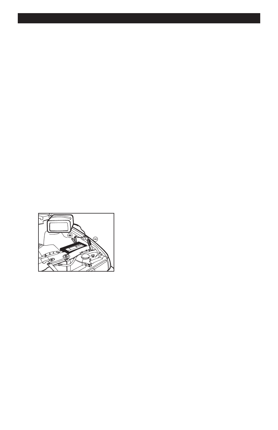
5.
Connecting to a negative-ground-
ed system: Connect the red (POSI-
TIVE) output clamp to the POSITIVE
post.of.the.battery..Rock.and.twist.
the.clamp.back.and.forth.to.be.sure.
a.solid.electrical.connection.is.made..
Then connect the black (NEGATIVE)
output.clamp.to.a.heavy,.unpainted.
metal.part.of.the.chassis.or.engine.
block, away from the battery (see fig-
ure above). DO NOT connect clamp
to.negative.battery.post,.carburetor,.
fuel.line.or.sheet.metal.part.
.
Connecting to a positive-grounded
system: Connect the black (NEGA-
TIVE) output clamp to the NEGA-
TIVE.post.of.the.battery..Rock.and.