StarTech.com ESY1525L User Manual
Page 25
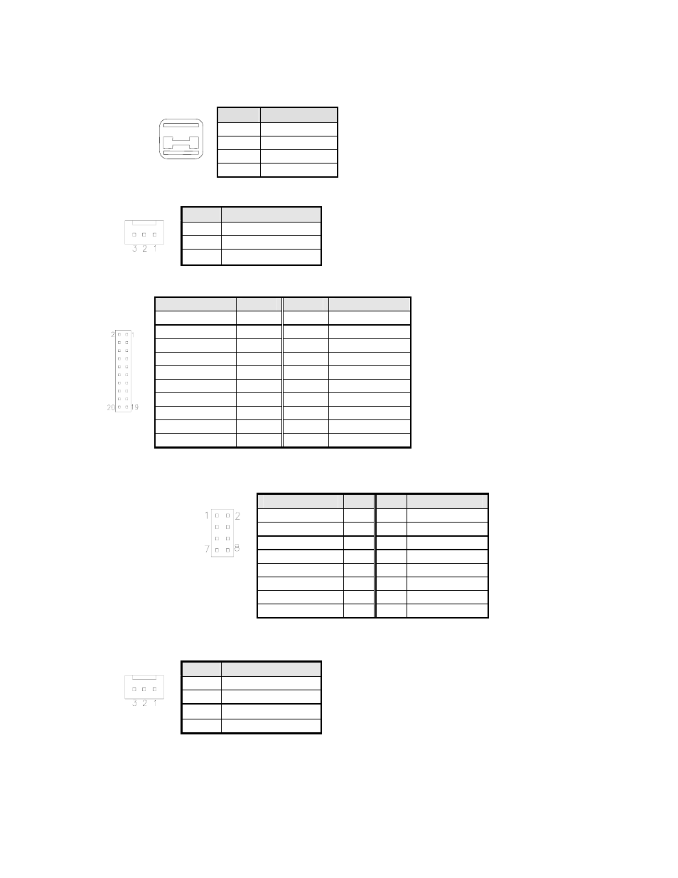
USB1, USB2: USB Connectors
Pin #
Signal Name
1 Vcc
2 USB-
3 USB+
4 Ground
J9: System Fan Power Connector
J9 is a 3-pin header for an optional fan. The fan must be a 12V fan.
Pin #
Signal Name
1 Ground
2 +12V
3 Rotation
detection
J11: 24-bit LVDS Connector (DF13-20)
Signal Name
Pin #
Pin #
Signal Name
TX0- 2
1 TX0+
Ground 4 3 Ground
TX1- 6
5 TX1+
5V/3.3V 8 7 Ground
TX3- 10
9 TX3+
TX2- 12
11 TX2+
Ground 14
13 Ground
TXC- 16
15 TXC+
5V/3.3V 18 17 ENABKL
+12V 20
19 +12V
J13: VGA CRT Connector
J13 is an 8-pin header for an optional external VGA CRT female connector.
Signal Name
Pin
Pin
Signal Name
Red 1
2 Vcc
Green 3
4
Ground
Blue 5
6 N.C.
N.C. 7
8 N.C.
Ground 9
10
H-Sync
Ground
11
12
V-Sync
Ground
13
14
N.C.
Ground 15
16 N.C.
J14: System Fan Power Connector
J14 is a 3-pin header for the optional system fan. The fan must be a 12V fan.
Pin #
Signal Name
1 Ground
2 +12V
3 Rotation
detection
4-20
E l o E n t u i t i v e T o u c h m o n i t o r U s e r G u i d e