Floppy connector, Ipmi 2.0 socket, Chapter 2: installation – SUPER MICRO Computer X6DHT-G User Manual
Page 49: Uper x6dht-g
Chapter 2: Installation
2-29
LAN1
®
JLAN1
S
UPER X6DHT-G
LAN2
DIMM 2A
DIMM 2B
DIMM 3A
DIMM 3B
DIMM 4A
DIMM 4B
DIMM 1B
DIMM 1A
12V 8-pin
P W R
SMBus
P W R
JF1
FP Control
OH
LED
IPMI
IDE2
Floppy
COM2
BIOS
Fan4
SATA0
SMB
PCI-X100 MHz
PCI-X 100 MHz/ZCR
PCI-X 3 133 MHz
Battery
JPL1
RAGE-
X L
PCI-E X8
Lindenhurst
North
Bridge
VGA
COM1
U S B
0/1
K B /
Mouse
Fan6 Fan5
ATX PWR
12V 4-Pin
PWR
Parrallel
Port
24-Pin
Fan7
JPW1
Fan8
CPU1
JWOR
S I/O
PSF
Fan3
IDE1
PCI-33 MHz
USB2/3
ICH
JD1
JPG1
J W D
Slot1
Slot2
Slot3
Slot4
Slot5
Slot6
PCI-E X8
GLAN
CTLR
6300ESB
Buzzer
P X H
JBT1
SATA1
SATA0
SATA1
SATA2
SATA3
SATA4
SATA5
SATA6
SATA7
Marvell
Intel
GLAN
CTLR
JPL2
M-SA
T
A
Act LED
J L 1
M-SA
T
A
I
2
C
JPS1
SATA
Controller
Fan2
Fan1
JAR
J3P
CPU2
E7520
Bank1
Bank2
Bank3
Bank4
WOL
DS9
DS1
DS10
DS2
DS11
DS3
DS12
DS4
DS13
DS5
DS14
DS6
DS15
DS7
DS16
DS8
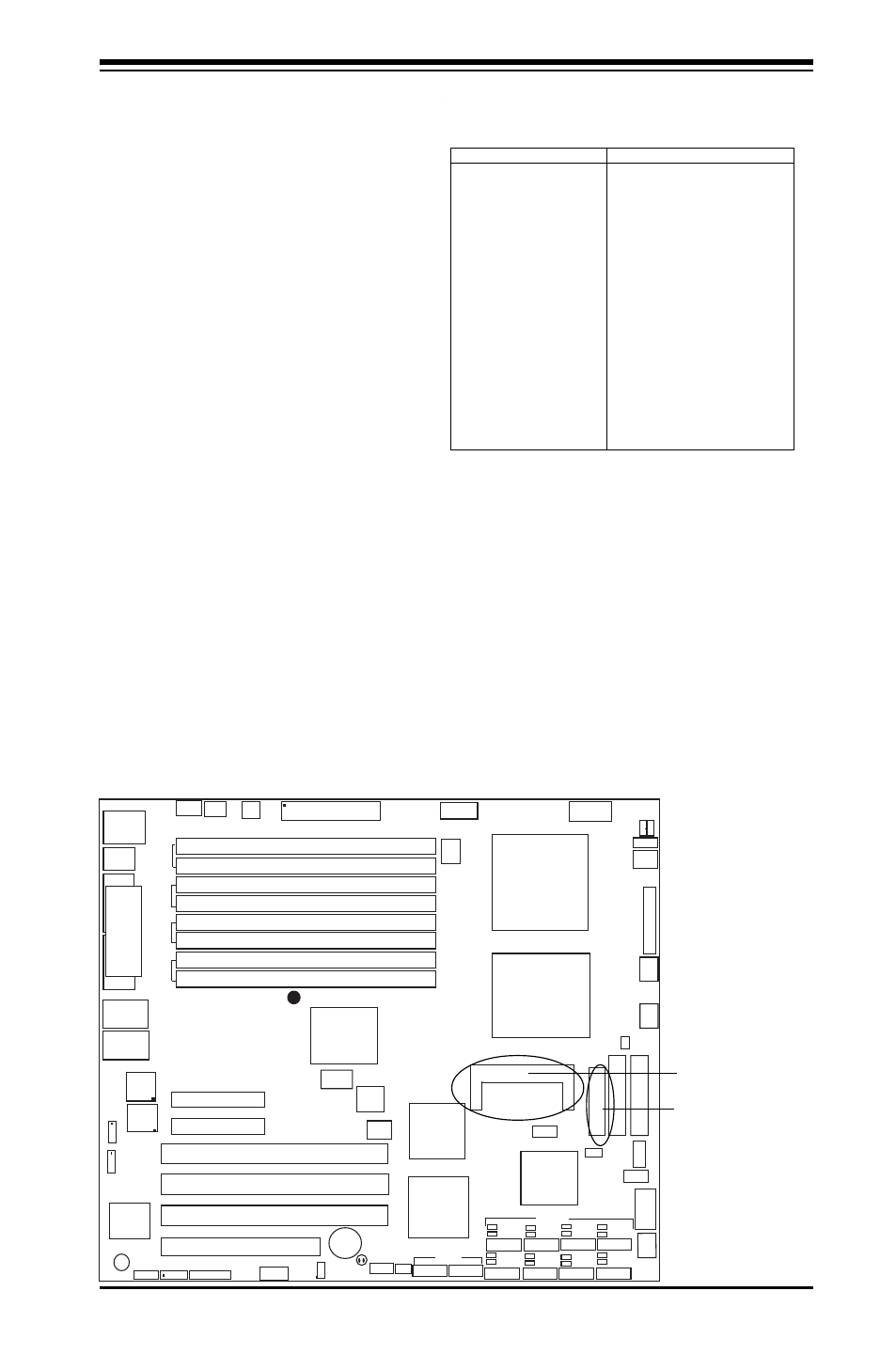
Floppy Connector
The floppy connector is lo-
cated between the IDE con-
nectors and the IPMI socket.
See the table below for pin
definitions.
Pin Number
Function
1
GND
3
GND
5
Key
7
GND
9
GND
11
GND
13
GND
15
GND
17
GND
19
GND
21
GND
23
GND
25
GND
27
GND
29
GND
31
GND
33
GND
Pin Number
Function
2
FDHDIN
4
Reserved
6
FDEDIN
8
Index-
10
Motor Enable
12
Drive Select B-
14
Drive Select A-
16
Motor Enable
18
DIR-
20
STEP-
22
W rite Data-
24
W rite Gate-
26
Track 00-
28
W rite Protect-
30
Read Data-
32
Side 1 Select-
34
Diskette
Floppy Connector Pin Definitions
Floppy
IPMI 2.0 Socket
The IPMI 2.0 Socket is located next to
the Floppy Drive. See the table below
for pin definitions.
IPMI 2.0